Method and System for Assigning Antennas in Dense Array

Active Publication Date: 2013-05-02
CHARTER COMM OPERATING LLC
View PDF8 Cites 9 Cited by
  • Summary
  • Abstract
  • Description
  • Claims
  • Application Information

AI Technical Summary

Benefits of technology

The patent text describes a system using small antenna elements and dense arrays to improve signal strength and compensate for signal loss. The system needs to be located close to the television transmitters to ensure a strong signal. This often results in the antennas being physically near the transmitters, which can make it difficult to install the system. The technical effect of the patent text is to improve the performance of small antenna systems by using dense arrays and ensuring strong signals even at long distances from the transmitters.

Problems solved by technology

Unlike antenna elements in a phased array, it is not desirable to have multiple antenna elements competing over the same incident power.
Additionally, it is not desirable to have antenna elements blocking lines of sights of other antenna elements tuned to receive same or similar channels.

Method used


Image

  • Method and System for Assigning Antennas in Dense Array
  • Method and System for Assigning Antennas in Dense Array
  • Method and System for Assigning Antennas in Dense Array

Examples


Embodiment Construction

[0017]The invention now will be described more fully hereinafter with reference to the accompanying drawings, in which illustrative embodiments of the invention are shown. This invention may, however, be embodied in many different forms and should not be construed as limited to the embodiments set forth herein; rather, these embodiments are provided so that this disclosure will be thorough and complete, and will fully convey the scope of the invention to those skilled in the art.

[0018]As used herein, the term “and / or” includes any and all combinations of one or more of the associated listed items. Further, the singular forms of nouns and the articles “a”, “an” and “the” are intended to include the plural forms as well, unless expressly stated otherwise. It will be further understood that the terms: includes, comprises, including and / or comprising, when used in this specification, specify the presence of stated features, integers, steps, operations, elements, and / or components, but d...


PUM


Abstract

A method and system optimally selecting antenna elements based on the current availability of antenna elements and the current usage of other antenna elements within a two or three dimensional array. The present system and method pertain to an approach to allow the maximal usage of each antenna element while simultaneously reducing the coupling between antenna elements to improve the signal strength in each antenna element by ensuring that antenna elements in the same incident path are not tuned to the same frequency or physically or electrically near elements tuned to identical or adjacent frequencies.

Description

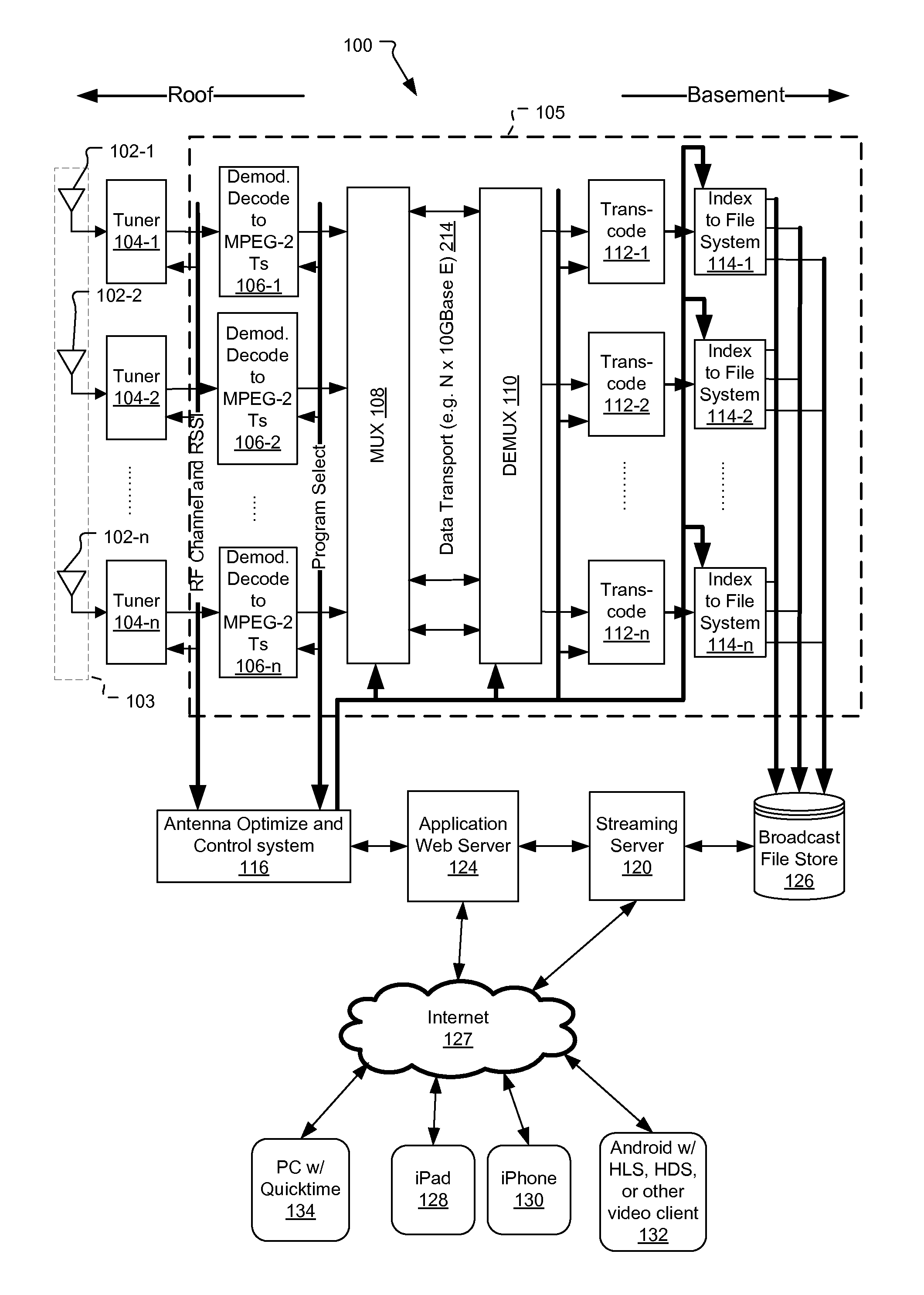
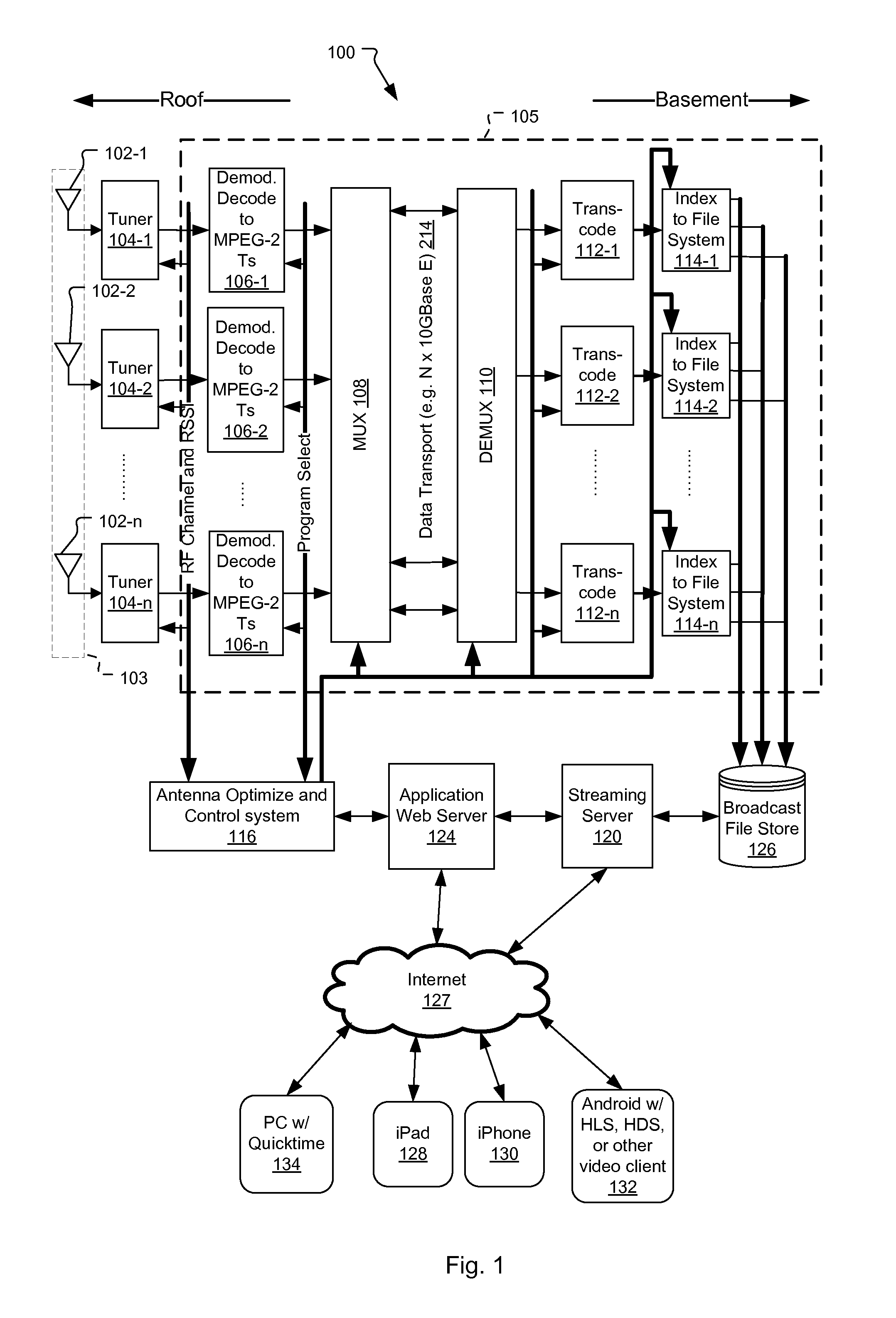
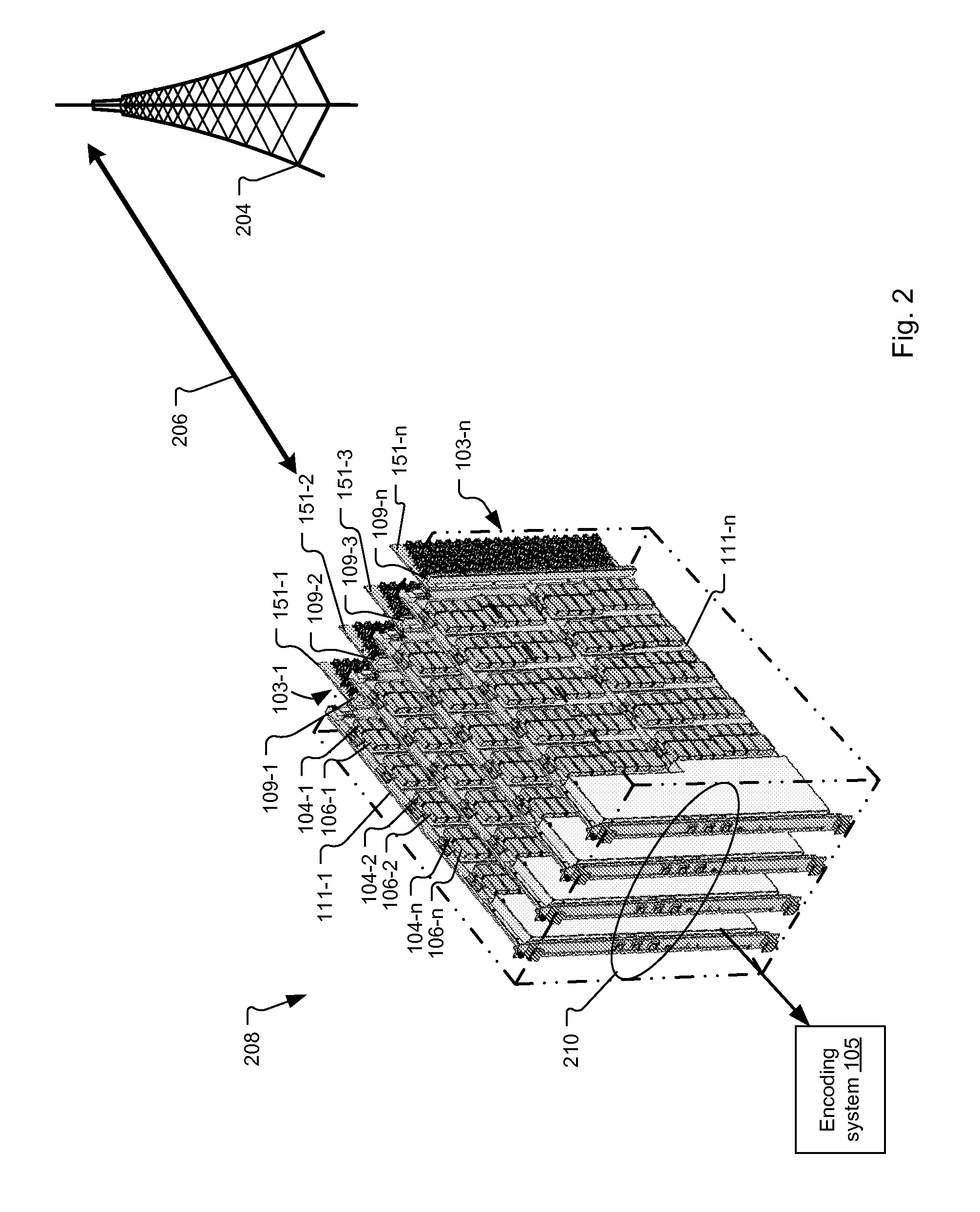
RELATED APPLICATIONS[0001]This application claims the benefit under 35 U.S.C. §119(e) of U.S. Provisional Application No. 61 / 551,756, filed on Oct. 26, 2011, which is incorporated herein by reference in its entirety.BACKGROUND OF THE INVENTION[0002]Recently, systems including arrays of small radio frequency (RF) antennas have been implemented for capturing over the air content, such as broadcast television. The systems then stream the captured content to users via a public network, such as the Internet. An example of a system for capturing and streaming over the air content to users via the Internet is described in, “System and Method for Providing Network Access to Antenna Feeds” by Kanojia et al., filed Nov. 17, 2011, U.S. patent application Ser. No. 13 / 299,186, (U.S. Pat. Pub. No.: US 2012 / 0127374 A1), which is incorporated herein by reference in its entirety.[0003]In typical capture systems, each user is assigned their own antenna element. Thus, the systems generally include two...

Claims


Application Information

Patent Timeline
IPC IPC(8): H04H20/46
CPCH04H20/423H04N21/2143H04N21/2393H04N21/2405H01Q1/523H04N21/43615H04N21/4383H04N21/64723H04N21/4263H04W72/30H04H60/17H04H60/27H04W72/046
Inventor LIPOWSKI, JOSEPH THADDEUSBINGHAM, JAMES ALAN
Owner CHARTER COMM OPERATING LLC
Why Eureka
Try Eureka