
Hydraulic antivibration device

a technology of anti-vibration and hydraulic pressure, which is applied in the direction of shock absorbers, machine supports, transportation and packaging, etc., can solve the problems of difficult to obtain a low dynamic spring characteristic, significant reduction of damping characteristic, and difficulty in alleviating hydraulic pressure differences, so as to reduce the working cost upon assembly, suppress the production of air pockets, and reduce the effect of strange sounds

Inactive Publication Date: 2006-05-11
TOYO TIRE & RUBBER CO LTD
View PDF8 Cites 31 Cited by
  • Summary
  • Abstract
  • Description
  • Claims
  • Application Information

AI Technical Summary

Benefits of technology

[0011] The present invention has been made to solve the problems described above, and accordingly, it is an object of the invention is to provide a hydraulic antivibration device that is capable of suppressing the generation of strange sounds while ensuring a low dynamic spring characteristic upon inputting of a relatively low amplitude vibration and a high damping characteristic upon inputting of a relatively high amplitude vibration.

Problems solved by technology

As a consequence, the problem here was that it was unable to exhibit sufficiently the fluidization effect of fluid, causing a significant reduction in damping characteristic.
Thus it was unable to transmit the hydraulic pressure variation between both liquid chambers efficiently to the elastic partition membrane, with the result that the hydraulic pressure difference was difficult to be alleviated by the elastic partition membrane and hence it was hard to obtain a low dynamic spring characteristic.
Further problem with the movable membrane structure was that because of the structure that the elastic partition membrane is made to abut against the displacement-regulating member, upon abutting thereof the displacement-regulating member is oscillated, which oscillation is transmitted to the body frame, thereby generating strange sounds.

Method used


Image

  • Hydraulic antivibration device
  • Hydraulic antivibration device
  • Hydraulic antivibration device

Examples


Embodiment Construction

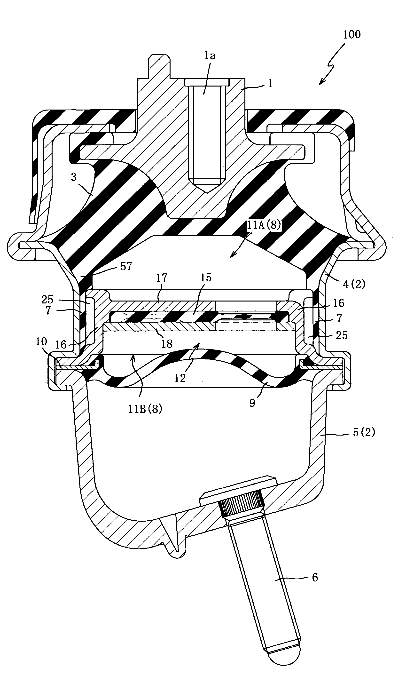
[0046] Preferred embodiments of the invention will be hereinafter described in more detail with reference to the accompanying drawings. Referring to FIG. 1, a hydraulic antivibration device 100 in one embodiment of this invention will be described.

[0047] The hydraulic antivibration device 100 is to support and secure an automotive engine so as not to transmit engine vibrations to the car body frame, and includes a first attachment fitting 1 to be attached to the engine side, a cylindrical second attachment fitting 2 to be attached to the car body frame side below the engine, and a vibration-isolating base 3 made of rubber-like elastomer interconnecting the both.

[0048] The first attachment fitting 1 is fashioned from a metal material such as aluminum in a generally columnar shape and is hollowed at its upper end face to be defined with a female part 1a, as shown. At the outer periphery of the first attachment fitting 1 there is formed a flange-like projecting portion, which is cons...


PUM


Abstract

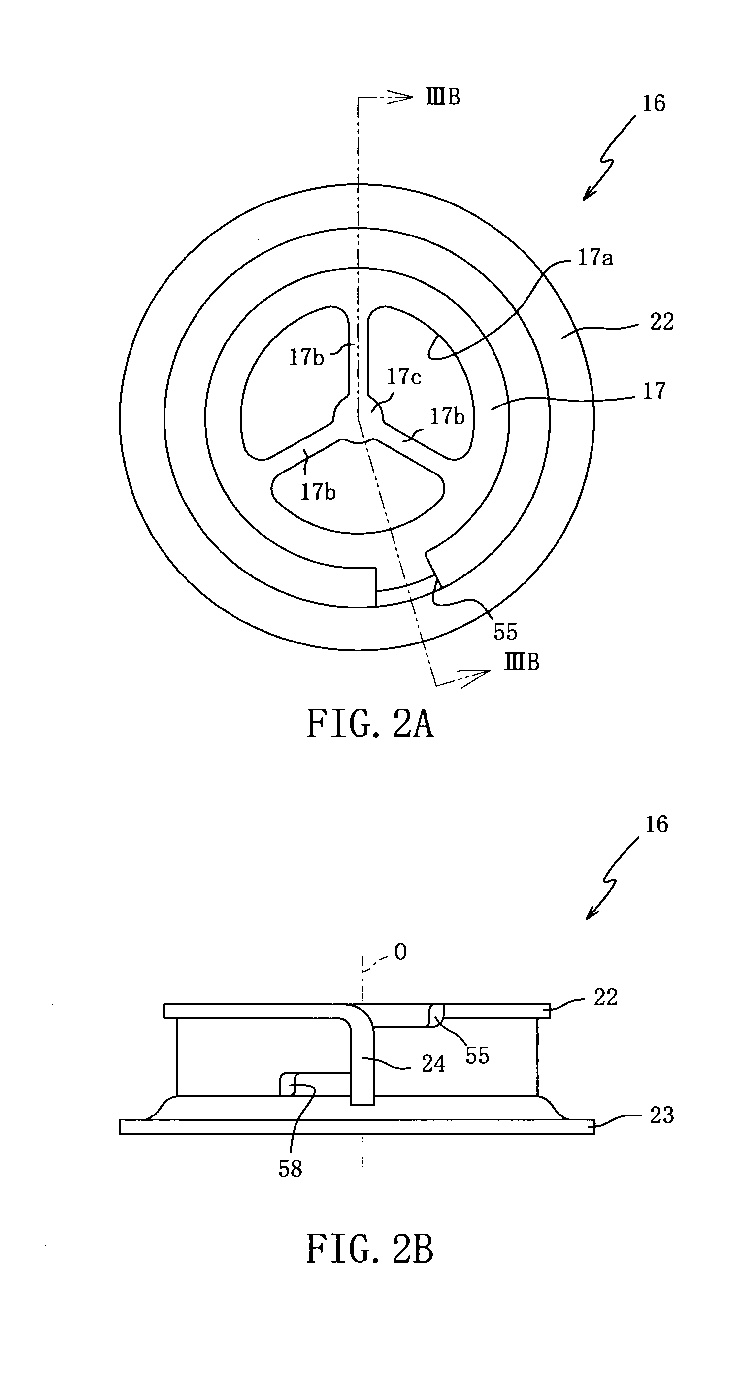
A hydraulic antivibration device is provided that is capable of suppressing generation of strange sounds while ensuring a low dynamic spring characteristic upon inputting of relatively small amplitude vibration and a high damping characteristic upon inputting of relatively large amplitude vibration. To that end, upon inputting of relatively large amplitude vibration, displacement-regulating ribs of one of sandwiching members serve to regulate displacement of an elastic partition membrane pinched by the sandwiching members thus obtaining a high damping characteristic. The displacement-regulating ribs consist of three pieces extending radially and rectilinearly, so that the area of openings of the sandwiching members is made wide enough to ensure more a low dynamic spring characteristic. Displacement-regulating protrusions of the elastic partition membrane are disposed to correspond to the displacement-regulating ribs thereby ensuring to suppress the generation of strange sounds.

Description

BACKGROUND OF THE INVENTION [0001] 1. Field of the Invention [0002] This invention relates to a hydraulic antivibration device, more particularly to such a hydraulic type of antivibration device that is capable of restraining the generation of strange or unusual sounds (noise) while ensuring a low dynamic spring characteristic upon inputting of vibrations of a relatively small amplitude and a high damping characteristic upon inputting of vibrations of a relatively large amplitude. [0003] 2. Description of Related Art [0004] As an antivibration device supporting and securing an automotive engine so as not to transmit the engine vibration to the body frame, a hydraulic type (liquid-filled type) of one is known. [0005] A typical hydraulic antivibration device is constructed so that a first attachment fitting to be mounted to the engine side and a second attachment fitting to be mounted to the body frame side are connected through a vibration-isolating base composed of rubber-like elast...

Claims


Application Information

Patent Timeline
Patent Type & Authority Applications(United States)
IPC IPC(8): F16F9/00F16F13/06F16F13/10
CPCF16F13/101F16F13/105F16F13/106F16F13/108
Inventor YAMAMOTO, KENTARO
Owner TOYO TIRE & RUBBER CO LTD
Learn More