
Ultraviolet transmitting near infrared cut filter glass

a filter glass and ultraviolet light technology, applied in the field of ultraviolet light transmitting near infrared cut filter glass, can solve problems such as heat deformation or temperature change, and achieve the effects of low light transmittance, high ultraviolet light transmittance, and high durability against irradiation

Inactive Publication Date: 2013-05-02
ASAHI GLASS CO LTD
View PDF0 Cites 27 Cited by
  • Summary
  • Abstract
  • Description
  • Claims
  • Application Information

AI Technical Summary

Benefits of technology

The present invention provides a way to make high-quality UV transmitting near infrared cut filter glass that is durable and can withstand high-power laser irradiation at a low cost. This is achieved by adjusting the composition of the glass phosphate and the melting atmosphere and temperature.

Problems solved by technology

However, in the case of wavelength conversion by using such a wavelength conversion element, not 100% of the incident fundamental wave (near infrared light) is converted and a part thereof is transmitted without being converted.
In such a case, an unintended near infrared light is applied to an object, and such may cause heat deformation or temperature change.

Method used


Image

  • Ultraviolet transmitting near infrared cut filter glass
  • Ultraviolet transmitting near infrared cut filter glass
  • Ultraviolet transmitting near infrared cut filter glass

Examples


examples

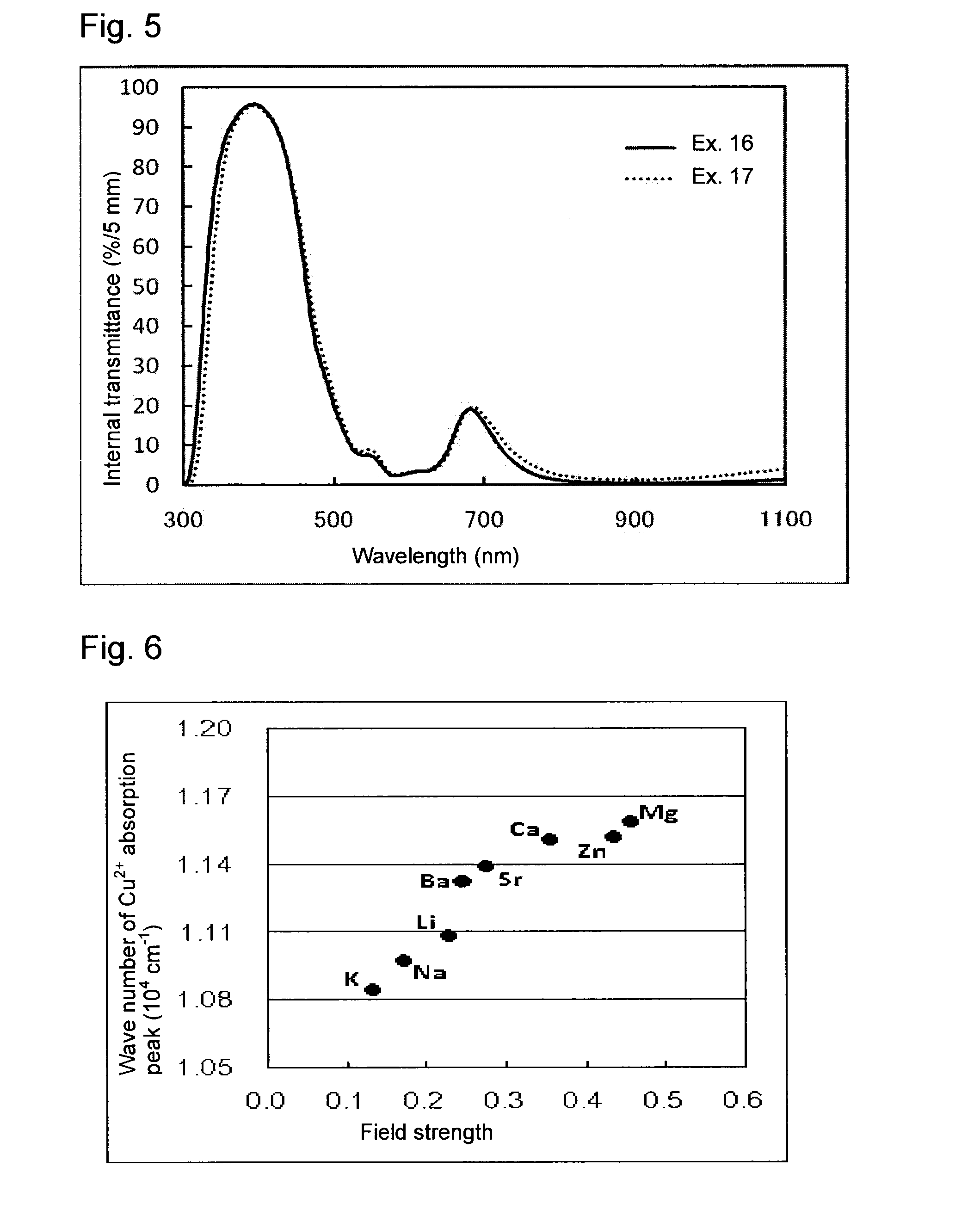
[0105]Examples of the present invention (Examples 1 to 4, 8 to 13, 16 and 17) and Comparative Examples (Examples 5 to 7, 14 and 15) are shown in Tables 1 to 4. In Tables, the internal transmittances at wavelengths λ=351 nm, 375 nm, 532 nm, 666 nm and 1,053 nm with a sample thickness of 5 mm are respectively abbreviated as T351, T375, T532, T666 and T1053. Chemical components in Tables 1 and 2 are represented by mass %, and chemical components in Tables 3 and 4 are represented by mol %. The melting temperature and the thickness when the internal transmittance at a wavelength of 1,053 nm becomes 5%, and the internal transmittance at a wavelength of 351 nm with this thickness, and the Pt ion concentration in Examples of the present invention (Examples 8 to 12, 18 and 19) are shown in Table 5. In Examples 18 and 19, the chemical composition is the same as in Example 10, and the melting temperature is different from that in Example 10.

[0106]The melting time, β-OH and the dew point in Exa...


PUM

PropertyMeasurementUnit
temperatureaaaaaaaaaa
internal transmittanceaaaaaaaaaa

Abstract

To provide a near infrared cut filter glass which can suppress the near infrared transmittance to be low while maintaining a high ultraviolet transmittance, at a low cost.Ultraviolet transmitting near infrared cut filter glass comprising, as represented by mass %, from 50 to 85% of P2O5, from 1 to 20% of Al2O3, from 1 to 5% of B2O3, from 0 to 2% of Li2O, from 0 to 15% of Na2O, from 0 to 20% of K2O, from 7 to 20% of Li2O+Na2O+K2O, from 0 to 2% of MgO, from 0 to 1% of CaO, from 0 to 4% of SrO, from 1 to 22% of BaO, from 1 to 22% of MgO+CaO+SrO+BaO, from 0.1 to 2% of CuO, from 0 to 1% of Co3O4 and from 0 to 5% of Sb2O3.

Description

TECHNICAL FIELD[0001]The present invention relates to ultraviolet transmitting near infrared cut filter glass to be used for high power laser optics.BACKGROUND ART[0002]In recent years, techniques employing a high power laser have attracted attention in various fields such as lithography for production of semiconductors, laser processing, laser fusion, medical technology and verification of pure science.[0003]Further, miniaturization of lithography and miniaturization of laser processing are in progress by employing a shorter laser wavelength and employing light in the ultraviolet region. By use of ultraviolet light, processing with suppressed influence by heat is possible, by which metals and glass and in addition, plastics and the like can also be processed. As such a high power ultraviolet laser, an excimer laser as a gas laser such as ArF (wavelength: 193 nm) or KrF (wavelength: 248 nm) may be mentioned. Further, YAG laser and YLF laser as a solid-state laser may also be mention...

Claims


Application Information

Patent Timeline
Patent Type & Authority Applications(United States)
IPC IPC(8): G02B5/22
CPCC03B32/00C03C3/17C03C3/19C03C4/0085G02B5/226C03C2203/54G02B5/208G02B5/22C03C4/082Y02P40/57
Inventor OGAWA, TOMONORIKOIKE, AKIOKONDO, YUKIOHKAWA, HIROYUKI
Owner ASAHI GLASS CO LTD
Learn More