
Magnetic dye-adsorbent catalyst

a dye-adsorbent catalyst and magnetic technology, applied in the direction of catalyst activation/preparation, metal/metal-oxide/metal-hydroxide catalysts, magnetic bodies, etc., can solve the problem of reducing the photosynthetic activity, affecting the photosynthesis effect, and containing textile dyes. , to achieve the effect of quick removal of organic textile dyes

Inactive Publication Date: 2013-05-02
COUNCIL OF SCI & IND RES
View PDF3 Cites 36 Cited by
  • Summary
  • Abstract
  • Description
  • Claims
  • Application Information

AI Technical Summary

Benefits of technology

The present invention aims to enhance the specific surface-area of conventional magnetic photocatalyst through a hydrothermal process, resulting in better removal of ions and dyes from surfaces. Additionally, a new washing cycle is developed to further improve the catalyst's effectiveness. The magnetic dye-adsorbent catalyst also exhibits faster removal of organic textile-dyes from an aqueous solution in the dark.

Problems solved by technology

Waste-water containing textile-dyes presents a serious environmental problem due to its high toxicity which leads to ground-water and surface-water pollution (1R.
Further, the discharge of colored effluents into water bodies affects the sunlight penetration which in turn decreases the photosynthetic activity.
1. Difficulties in removing TiO2-based fine photocatalyst particles from the treated effluent after the completion of photocatalysis treatment.
Traditional methods for the solid-liquid separation such as coagulation, flocculation, and sedimentation are tedious and expensive to apply in a photocatalytic process.
6. An energy-dependent process, that is, requiring an exposure to the ultraviolet (UV), visible, or solar-radiation, the photocatalytic degradation mechanism is an expensive process for the commercial utilization.
This has been mainly due to the non-suitability of the conventional magnetic photocatalyst for the surface-adsorption mechanism as a result of its lower specific surface-area.

Method used


Image

  • Magnetic dye-adsorbent catalyst
  • Magnetic dye-adsorbent catalyst
  • Magnetic dye-adsorbent catalyst

Examples


example — 1

EXAMPLE—1

[0077]In a typical procedure, 36.94 g of citric acid (S.D. Fine Chemicals Ltd., India)) was dissolved in 40 ml of ethylene glycol (S.D. fine chemicals Ltd., India) (in the molar ratio of 1:4) to get a clear solution. 17 g of cobalt(II) nitrate (Co(NO3)2.6H2O, Sigma-Aldrich, India) and iron(III) nitrate (Fe(NO3)3).9H2O) (47.35 g, Sigma-Aldrich, India) were added to the above solution and stirred for 1 h. The resulting solution was then heated at 80° C. for 4 h in an oil bath under continuous stirring. The yellowish gel thus obtained was charred at 300° C. for 1 h in a vacuum furnace. A black colored solid precursor was obtained, which was then ground in an agate mortar and heat treated at 600° C. for 6 h.

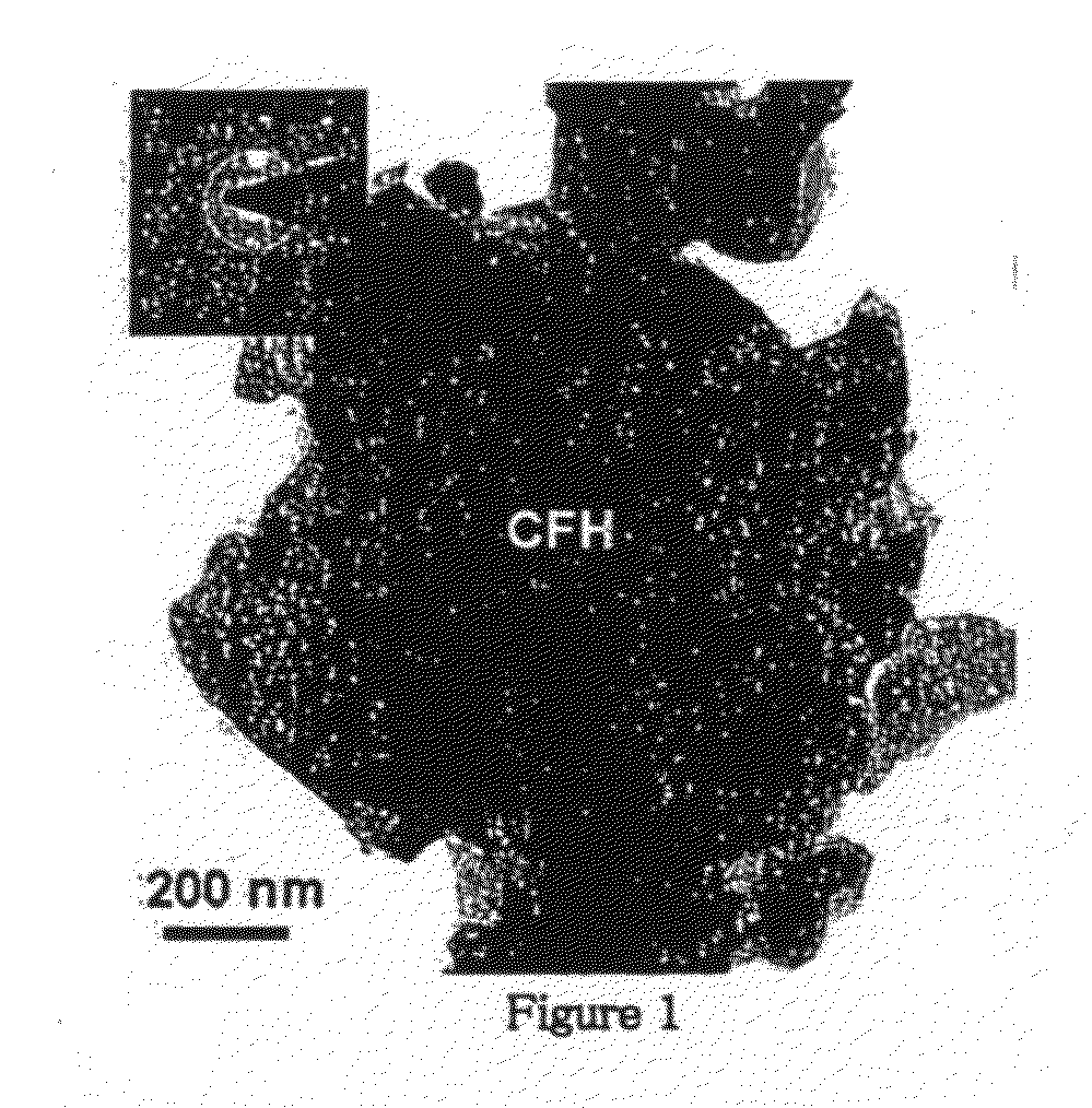
[0078]The TEM micrograph of the obtained powder is shown in FIG. 1, where the aggregate size as large as ˜1 μm is noted. The edges magnetic particles are relatively straight, smooth, and featureless. The corresponding SAED pattern is shown as an inset in FIG. 1, which shows ...

example — 2

EXAMPLE—2

[0095]In this example, pure-CoFe2O4 magnetic particles were used instead of CoFe2O4—Fe2O3 magnetic particles as used in the previous example. The TiO2-coating on the surface of pure-CoFe2O4 magnetic particles were obtained via sol-gel using the Ti(OC3H5)4 precursor with the R-value of 10 (Larger R-values normally result in the precipitation of free-TiO2 particles without forming any coating on the surface of magnetic particles). The concentration of Ti(OC3H5)4 was reduced to 0.5 g·L−1 and the sol-gel process was repeated twice to obtain a thicker TiO2-coating. 15 wt. % TiO2 was deposited on the SiO2 / CoFe2O4 magnetic particles as derived from an increase in the weight of the sample. All remaining processing and test parameters were similar to those used in the previous example.

[0096]The XRD pattern obtained for the pure-CoFe2O4 magnetic particles is presented in FIG. 11, where the peaks are identified to correspond to those of pure-CoFe2O4 after comparing the pattern with th...

example — 3

EXAMPLE—3

[0099]In this example, the catalytic nature of the new magnetic dye-adsorbent catalyst has been demonstrated. All processing and test parameters were similar to those used in the example—2. The high surface-area new magnetic dye-adsorbent catalyst (calcined-sample) was utilized for the successive five cycles of MB dye-adsorption experiments conducted in the dark.

[0100]The quantitative variation in the normalized concentration of surface-adsorbed MB as a function of stirring time in the dark, as obtained for the different number of cycles. It is noted that, with increasing number of dye-adsorption cycles from cycle-1 to cycle-5, conducted in the dark, the maximum normalized concentration of MB dye adsorption decreases progressively from 95% to 60%. This clearly shows very high dye-adsorption capacity of the high surface-area new magnetic dye-adsorbent catalyst for the repeated number of dye-adsorption cycles.

[0101]To remove the previously adsorbed MB dye from the surface and...


PUM

PropertyMeasurementUnit
Temperatureaaaaaaaaaa

Abstract

New magnetic dye-adsorbent catalyst has been described in this invention, which is the modification of conventional magnetic photocatalyst. The catalyst consists of a composite particle having a core-shell structure, with a magnetic particle as a core and a dye-adsorbent (which may also exhibit photocatalytic activity) as a shell. The shell is made up of 1-dimensional (1-D) nanostructure, which enhances the specific surface-area of the conventional magnetic photocatalyst. The new magnetic dye-adsorbent catalyst removes an organic dye from an aqueous solution via surface-adsorption mechanism; while, the conventional magnetic photocatalyst uses the photocatalytic degradation mechanism.

Description

FIELD OF THE INVENTION[0001]The present invention relates to preparation of a magnetic dye-adsorbent catalyst. More particularly, this invention is useful for the industrial waste-water purification involving the removal of harmful organic textile-dyes through the surface-adsorption mechanism using a high surface-area new magnetic dye-adsorbent catalyst.BACKGROUND OF INVENTION[0002]Water purification via photocatalysis has gained significant attention over the past three decades. Waste-water containing textile-dyes presents a serious environmental problem due to its high toxicity which leads to ground-water and surface-water pollution (1R. Amal, D. Beydoun, G. Low, S. Mcevoy, U.S. Pat. No. 6,558,553; 2P. A. Pekasis, N. P. Xekoukoulotakis, D. Mantzavinos, Water Research 2006, 40, 1276-1286). Further, the discharge of colored effluents into water bodies affects the sunlight penetration which in turn decreases the photosynthetic activity. Therefore, the removal of highly stable organic...

Claims


Application Information

Patent Timeline
IPC IPC(8): B01J20/28C02F1/28B01J35/02
CPCB01J13/20B82Y30/00B01J20/28009B01J21/063B01J23/745B01J23/75B01J23/78B01J23/80B01J23/835B01J23/8892B01J27/043B01J35/0013B01J35/0033B01J35/004B01J35/008B01J35/023B01J35/10B01J37/0244B01J37/10C02F1/281C02F1/288C02F1/30C02F1/32C02F1/488C02F2101/308C02F2103/30C02F2305/08C02F2305/10B01J20/28016B01J35/026C02F1/28B01J20/02B01J20/28007B01J20/3204B01J20/3236B01J20/3293B01J2220/42B01J20/06Y02W10/37B01J13/02B01J13/22B01J20/08B01J20/3078B01J20/103B01J35/397B01J35/23B01J35/33B01J35/60B01J35/40B01J35/39B01J35/50
Inventor SHUKLA, SATYAJIT V.WARRIER, KRISHNA G.VARMA, MANOJ R.LAJINA, MADADHIN T.HARSHA, NARAYANICHALAPPURATH, PATTELATH R.
Owner COUNCIL OF SCI & IND RES
Learn More