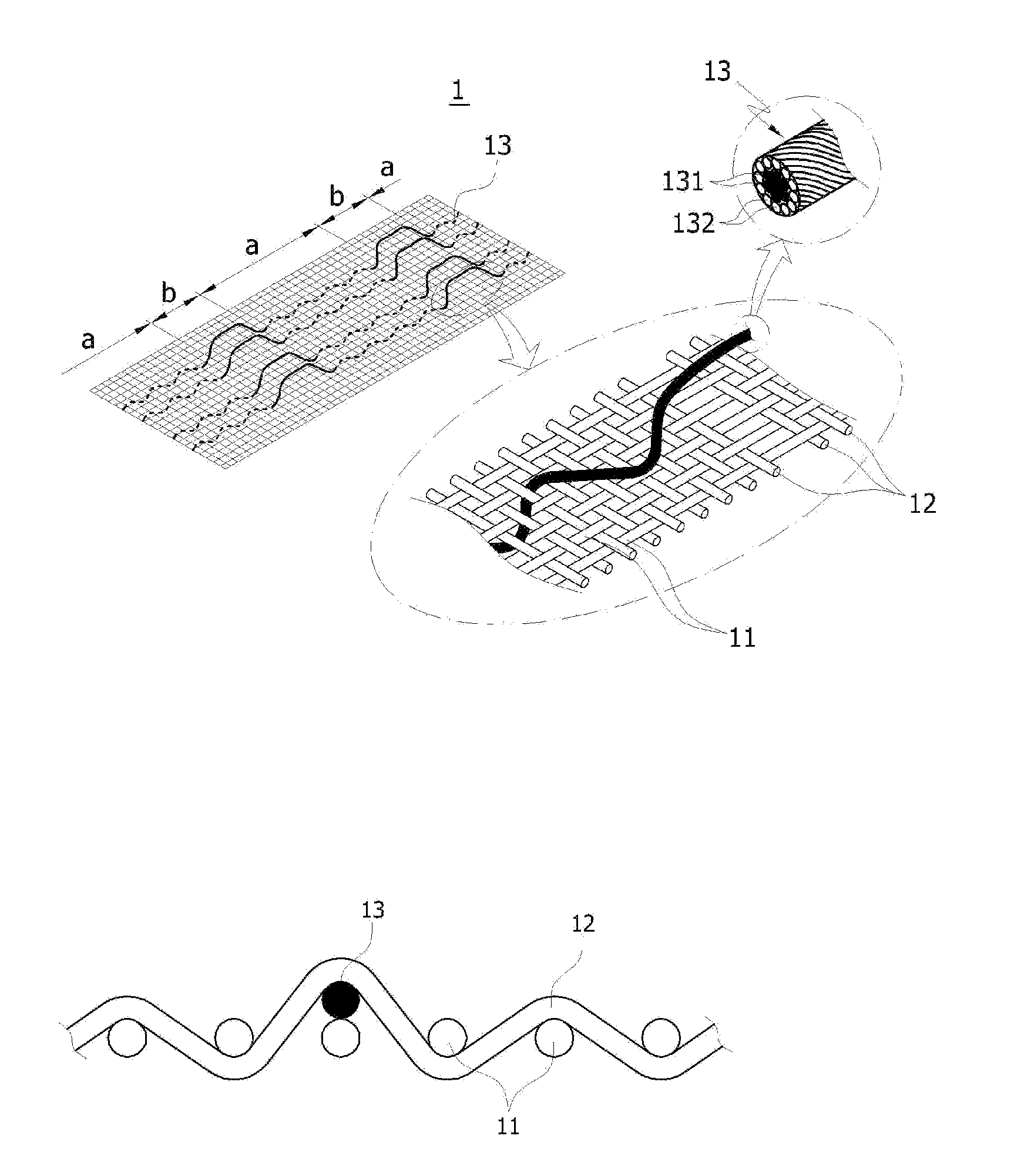

Electrically conductive fabric and manufacturing method and apparatus thereof

Inactive Publication Date: 2013-04-25
SILVERAY CO LTD
View PDF5 Cites 74 Cited by
  • Summary
  • Abstract
  • Description
  • Claims
  • Application Information

AI Technical Summary

Benefits of technology

The present invention provides an electrically conductive fabric and a method and apparatus for its manufacturing. The fabric has electrically conductive wire exposing sections where wires are not knitted, making it easy to connect components. The fabric's weaving sections allow for quick and convenient tying or connecting work, improving workability and productivity in the use of electrically conductive fabrics.

Problems solved by technology

Such a planar heating unit woven by carbon fiber yarn performs heating action when power is supplied, so it can be applied to the goods that need warming action, but it has a disadvantage that it cannot be applied to bed material that needs a cushioning function or clothes that need stretchability and freedom of motion because it does not have stretchability at all due to the characteristics of carbon fiber yarn.
And if friction force is applied continuously while it is being used, the fine structures of carbon fiber yarn become loosened and damaged or minute electrical sparks are generated, so it was not possible to secure sufficient durability and safety.
In addition, smart clothes equipped with electronic appliances such as a wearable computer and an MP3 player need conductive wires for electrically connecting operating buttons, power supply unit, various electronic elements, etc. and for transmitting electric signals, but a planar heating unit manufactured with carbon fiber yarn has a limit that it cannot perform such functions at all.
As a way for solving such problems, a method of stitching an extra conductive wire such as copper wire to clothes can be suggested, but because a copper wire does not have any stretchability at all, the freedom of motion and wearability as clothes are not good.
Another disadvantage is that it is very inconvenient to use it because the conductive wire and control buttons installed in the clothes have to be removed to wash them.
However, the electrically conductive fabrics that the present applicant earlier filed for a patent therefor has a disadvantage that it is cumbersome to do the work of tying the woven conductive wire together with the fabric yarn into a fabric to configure connection or a circuit with the power supply unit or the work of connecting various elements or modules.
In other words, because the worker has to find one by one the electrically conductive wires contained in the fiber yarn configuring electrically conductive woven fabrics to connect each other, it has disadvantages that the work of finding the electrically conductive wires is hard and takes time so as to cause the deterioration of workability and productivity and the fiber yarns nearby are damaged in the course of finding the electrically conductive wires.

Method used

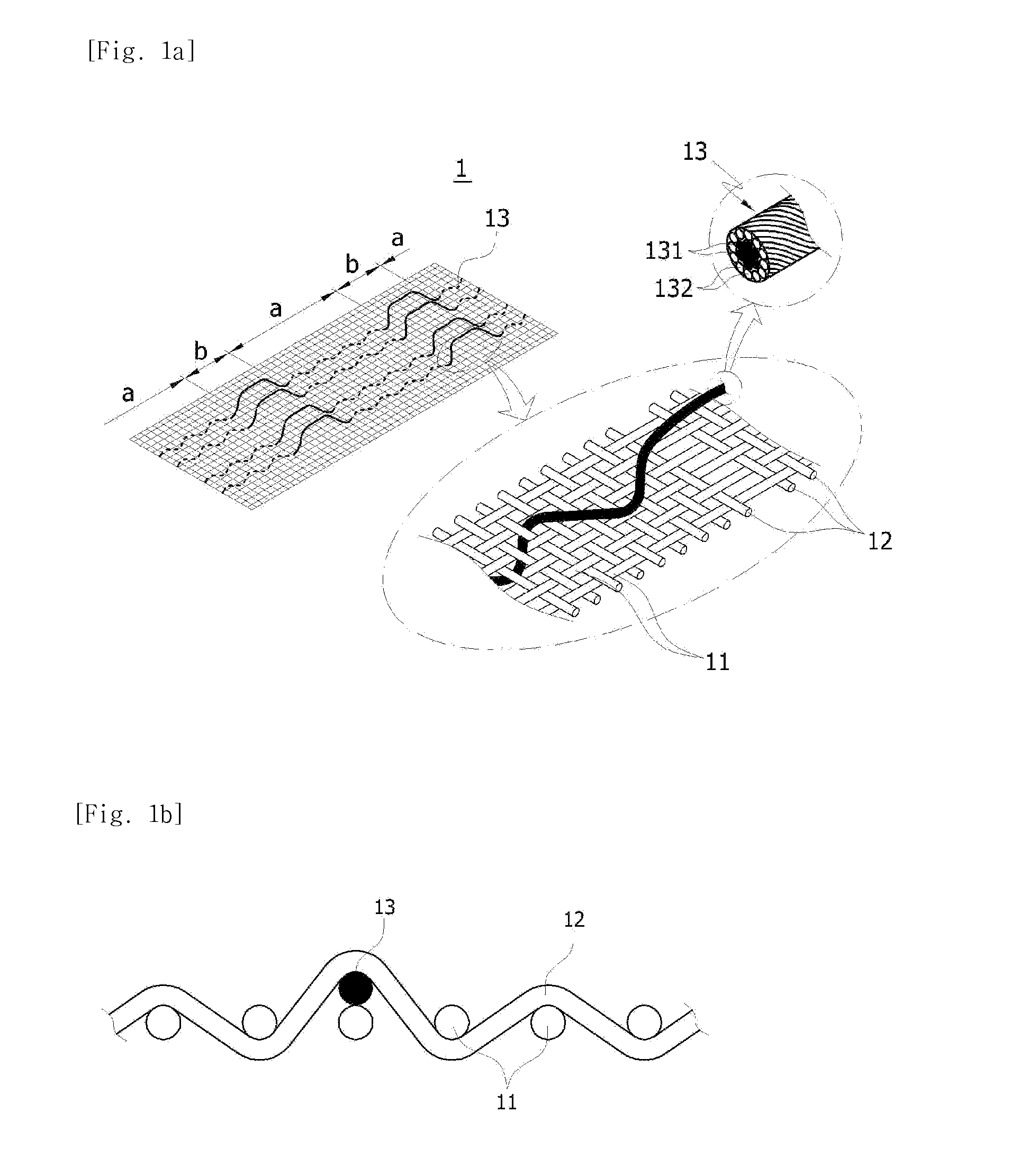

Image

  • Electrically conductive fabric and manufacturing method and apparatus thereof
  • Electrically conductive fabric and manufacturing method and apparatus thereof
  • Electrically conductive fabric and manufacturing method and apparatus thereof

Examples


first embodiment

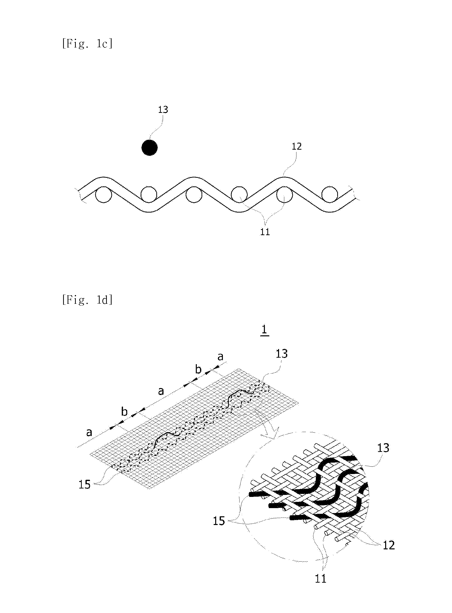
[0045]Next, FIG. 1d is a view showing the first modification of the electrically conductive fabric according to the present invention; as shown in the drawing, the electrically conductive fabric includes support wires 15 which are woven along the placement path of the electrically conductive wire.

[0046]The support wires 15 are woven on the left and right of the electrically conductive wire 13 to bind it to the warp and weft so as to prevent deformation. Namely, if the electrically conductive wire 13 is composed of metal yarn, it is protruded to the surface or back of the electrically conductive fabric 1 due to the difference in flexibility from the fiber yarn supplied as the weft and warp. At this time, since the support wires 15 perform the function of holding the weft and warp on the left and right as reinforcement wires, the twist of the electrically conductive wire can be prevented. For this purpose, it is preferable that the support wire 15 has a plurality of fiber yarns twiste...

second embodiment

[0053]With reference to FIGS. 2a to 2c and FIG. 2d, the electrically conductive fabric 1′ according to the present invention includes multiple strands of warp 11 arranged lengthwise, multiple strands of weft 12 knitted in the direction perpendicular to the warp 11, and plural strands of electrically conductive wires 13 arranged lengthwise and woven. At this time, the weft 12 includes a first warp-knitting weft 12a that is knitted with the warp 11 at the position corresponding to the inside of the electrically conductive wire 13, a second weft 12b (see FIG. 2d) for knitting the warp that is knitted with the warp 13 so as to provide a feeding free zone in the range of width corresponding to the placement width of the electrically conductive wire 13 at the position corresponding to the outside of the electrically conductive wire 13, and a binding-and-releasing weft 12c (see FIGS. 2b and 2c) that is knitted with the warp so as to selectively bind the electrically conductive wire 13 at t...


PUM

PropertyMeasurementUnit
Lengthaaaaaaaaaa
Electrical conductivityaaaaaaaaaa
Electrical conductoraaaaaaaaaa

Abstract

The present invention discloses to relates to an electrically conductive fabric, and a manufacturing method and an apparatus thereof, and more specifically to an electrically conductive fabric, and a manufacturing method and an apparatus thereof, wherein part of electrically conductive wire woven together into fabric is selectively exposed to the outside of the fabric to perform the tying of electrically conductive wires and the connection of various elements and modules quickly and conveniently, so that workability and productivity can be improved.

Description

TECHNICAL FIELD[0001]The present invention relates to an electrically conductive fabric, and a manufacturing method and an apparatus thereof, and more specifically to an electrically conductive fabric, and a manufacturing method and an apparatus thereof, wherein part of electrically conductive wire woven together into fabric is selectively exposed to the outside of the fabric to perform the tying of electrically conductive wires and the connection of various elements and modules quickly and conveniently, so that workability and productivity can be improved.BACKGROUND ART[0002]In general, fabrics such as knitted fabrics or woven fabrics (below to be described commonly as fabrics) that are used to manufacture bed covers, curtains, clothes, etc. are woven by natural fiber yarn or man-made fiber yarn, and their kinds are various, and they have properties and characteristics unique in their own way according to the purpose of use, such as heat conservation, absorptivity, stretchability, ...

Claims


Application Information

Patent Timeline
IPC IPC(8): D03D15/00D03D1/00D03D15/56
CPCD03D15/0027D03D27/06D04B21/14D10B2401/16D10B2101/20D03D15/00D03D1/0088D03D13/004D03D15/02D03D1/00Y10T442/3008Y10T442/3073Y10T442/3195Y10T442/3179D03D15/47D03D15/25D03D15/533D03D13/00D03D15/56D02G3/38D10B2401/18
Inventor JEON, BYUNG-OK
Owner SILVERAY CO LTD
Learn More