Navigating an interventional device

a technology of interventional devices and navigation devices, which is applied in the field of navigation interventional devices, can solve problems such as cluttering of interventional images, and achieve the effects of convenient interventional procedures, improved detection, and easy readable image information

Active Publication Date: 2013-04-25
KONINKLIJKE PHILIPS ELECTRONICS NV
View PDF11 Cites 5 Cited by
  • Summary
  • Abstract
  • Description
  • Claims
  • Application Information

AI Technical Summary

Benefits of technology

The patent describes a system that provides enhanced information to an operator by mapping the determined position of an X-ray fluoroscopy image to a position in a 3D data set. This allows the operator to easily understand the necessary three-dimensional information for navigating a device through a vessel tree or other structure. The system can continuously acquire X-ray fluoroscopy images to track the device position and the related position in the 3D data set, providing real-time information to the operator. The system can also use the device as a pointer in the 3D data set, providing a better understanding of the local shape of the vessel tree or other structure. The system can also optimize the view angle of the device to improve the visibility and reduce the chance of misinterpretation. Overall, the system improves the efficiency and accuracy of interventional procedures.

Problems solved by technology

However, the projected roadmap is still a 2D “flat” representation of the vessels which does not provide depth information.
Additionally, overlaying the footprint of the vessels tends to clutter the interventional image, which should be left as clean as possible.

Method used


Image

  • Navigating an interventional device
  • Navigating an interventional device
  • Navigating an interventional device

Examples


Embodiment Construction

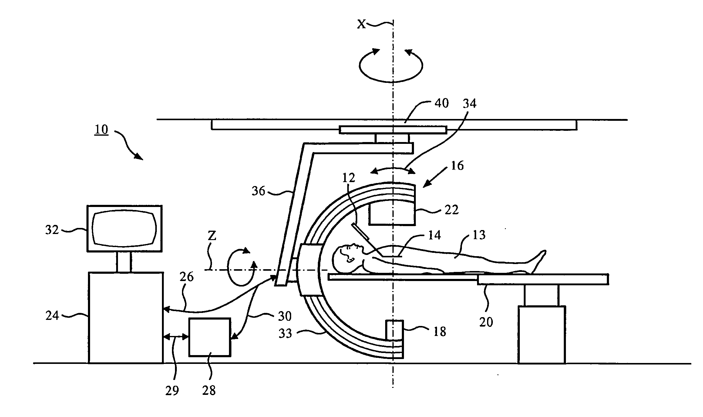
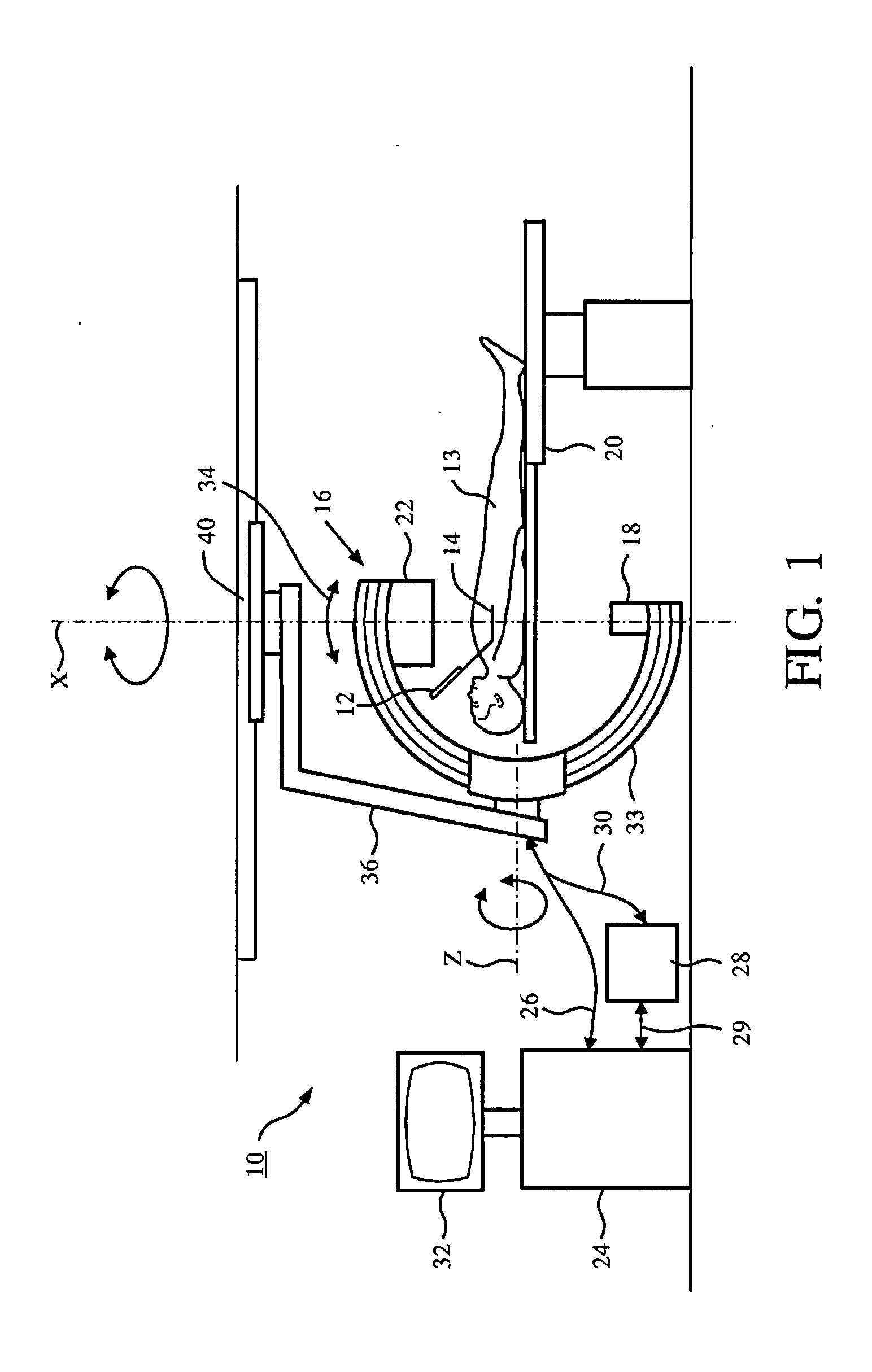
[0105]FIG. 1 schematically shows a system 10 for navigating an interventional device 12 within a tubular structure of an object, for example a patient 13. As an example, the interventional device is a guide-wire for percutaneous coronary interventions. The guide wire has a tip, indicated with reference number 14, but not further shown. The system 10 comprises an X-ray image acquisition device 16 with a source of X-ray radiation 18 provided to generate X-ray radiation. A table 20 is provided to receive a subject to be examined, for example the patient 13. Further, the X-ray image acquisition device 16 comprises a detection module 22 located opposite the source of X-ray radiation 18, i.e. during the radiation procedure, the subject or patient 13 is located between the source of X-ray radiation 18 and the detection module 22. The latter is sending data to a control unit or processing unit 24 connected to the X-ray image acquisition device 16 by a cable connection 26. Of course, the cab...


PUM


Abstract

The present invention relates to navigating an interventional device. In particular, the invention relates to a system for navigating an interventional device within a tubular structure of an object, a method for navigating an interventional device within a tubular structure of an object as well as a computer program element and a computer-readable medium. In order to provide enhanced information to the user in an easily comprehensible manner while keeping the X-ray dose to a minimum, a system and a method for navigating an interventional device within a tubular structure of an object are provided, wherein the method comprised the following steps: a) Acquiring 2D X-ray fluoroscopy image data in one projection geometry of a region of interest of the tubular structure; b) detecting the interventional device in the 2D X-ray image; c) determining the 2D position of the interventional device in the 2D X-ray image; d) registering the at least one 2D X-ray image with a previously acquired 3D dataset of the region of interest of the tubular structure; e) mapping the determined 2D position of the interventional device to a position in the 3D dataset; f) extracting local 3D parameters of the tubular structure at the position of the interventional device; g) generating navigational information on behalf of the determined 3D position of the interventional device and the extracted local 3D parameters; and h) providing the navigational information to the user.

Description

FIELD OF THE INVENTION[0001]The present invention relates to navigating an interventional device. In particular, the invention relates to a system for navigating an interventional device within a tubular structure of an object, a method for navigating an interventional device within a tubular structure of an object as well as a computer program element and a computer-readable medium.BACKGROUND OF THE INVENTION[0002]In order to use interventional devices in tubular structures where the location of the device is not visible to the user from the outside of the object, the user is provided with information about the location of the device in relation to the object. For example, during neurological interventions, devices are routinely used in the treatment process of diseased vessels. In order to assist the physician, for example a neurosurgeon, with navigating a specific device to the diseased vessel segment, the device and region of interest are visualized using X-ray imaging. For exam...

Claims


Application Information

Patent Timeline
Patent Type & Authority Applications(United States)
IPC IPC(8): G06T11/00A61B6/00
CPCG06T7/0024G06T11/008G06T2207/10072G06T2207/10121Y10S128/922G06T2211/404G06T2211/428A61B6/52G06T11/003G06T2207/30101G06T7/30
Inventor FLORENT, RAOULSCHOOENENBERG, GERT ANTONIUS FRANCISCUSVAN RENS, BRAM ANTONIUS PHILOMENA
Owner KONINKLIJKE PHILIPS ELECTRONICS NV
Why Eureka
Try Eureka