
Temperature Compensation in a Semiconductor Micromechanical Resonator Via Charge Carrier Depletion

a micromechanical resonator and temperature compensation technology, applied in the direction of generator/motor, device details, device details, etc., can solve the problems of reducing the q of the resonator, impractical compensating materials with positive tcf on silicon, etc., and achieve the effect of minimizing the flow of free charge carriers

Active Publication Date: 2013-04-25
GEORGIA TECH RES CORP
View PDF9 Cites 12 Cited by
  • Summary
  • Abstract
  • Description
  • Claims
  • Application Information

AI Technical Summary

Benefits of technology

The patent text discusses a method for temperature compensation in silicon micromechanical resonators without compromising their quality factor. This can be achieved by minimizing the flow of free charge carriers in the resonators, which can be achieved by degenerate doping or creating a pn-junction based free charge carrier depletion region. The technical effects include improved accuracy and stability of temperature compensation in silicon resonators.

Problems solved by technology

Circuit-based compensation techniques add to the power budget whereas depositing compensating materials with positive TCF on silicon is impractical on certain resonator geometries and may reduce the Q of the resonator.

Method used


Image

  • Temperature Compensation in a Semiconductor Micromechanical Resonator Via Charge Carrier Depletion
  • Temperature Compensation in a Semiconductor Micromechanical Resonator Via Charge Carrier Depletion
  • Temperature Compensation in a Semiconductor Micromechanical Resonator Via Charge Carrier Depletion

Examples


Embodiment Construction

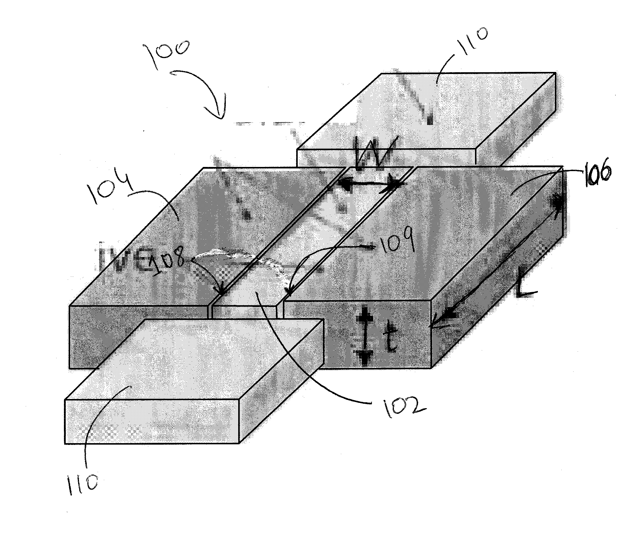
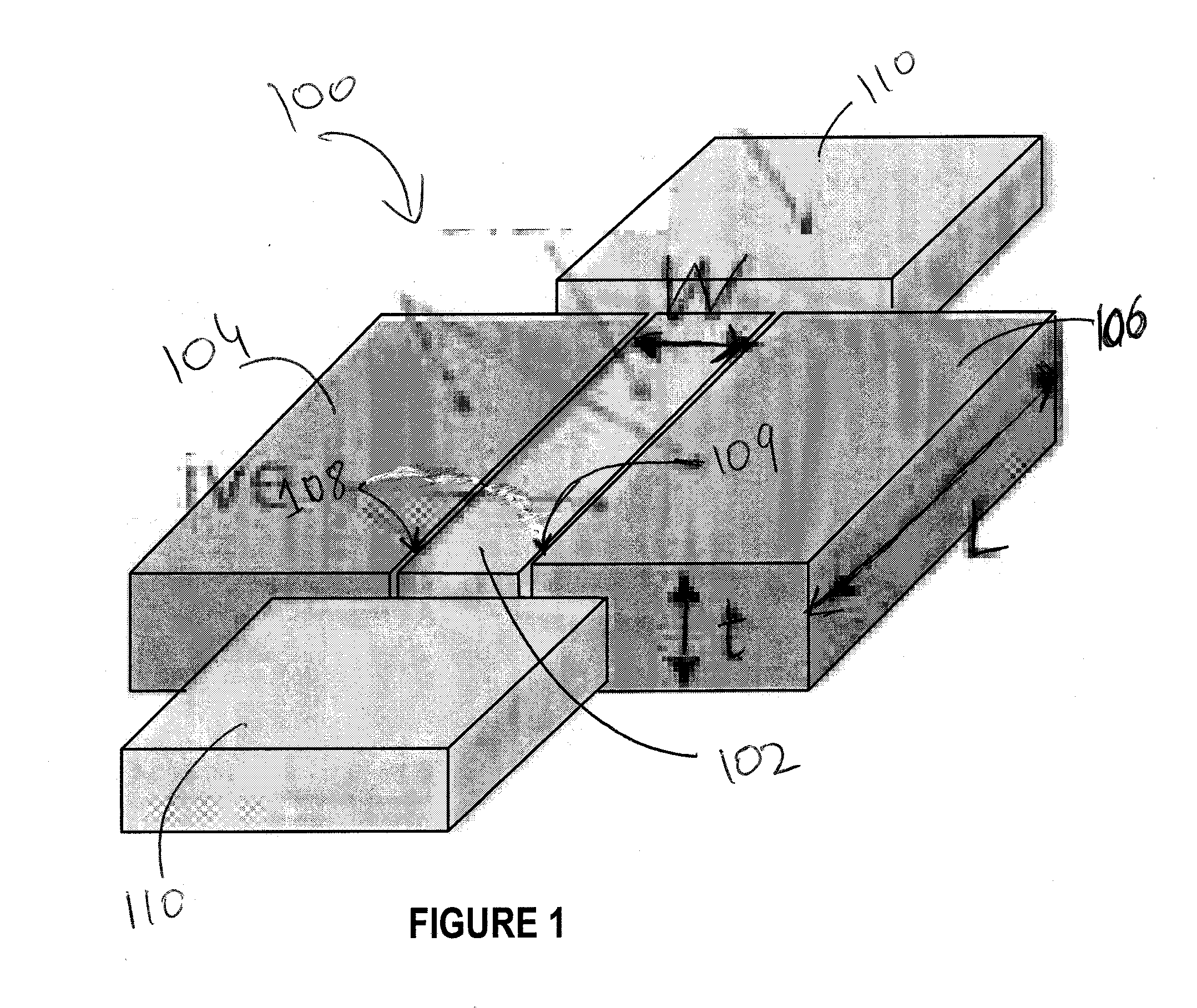
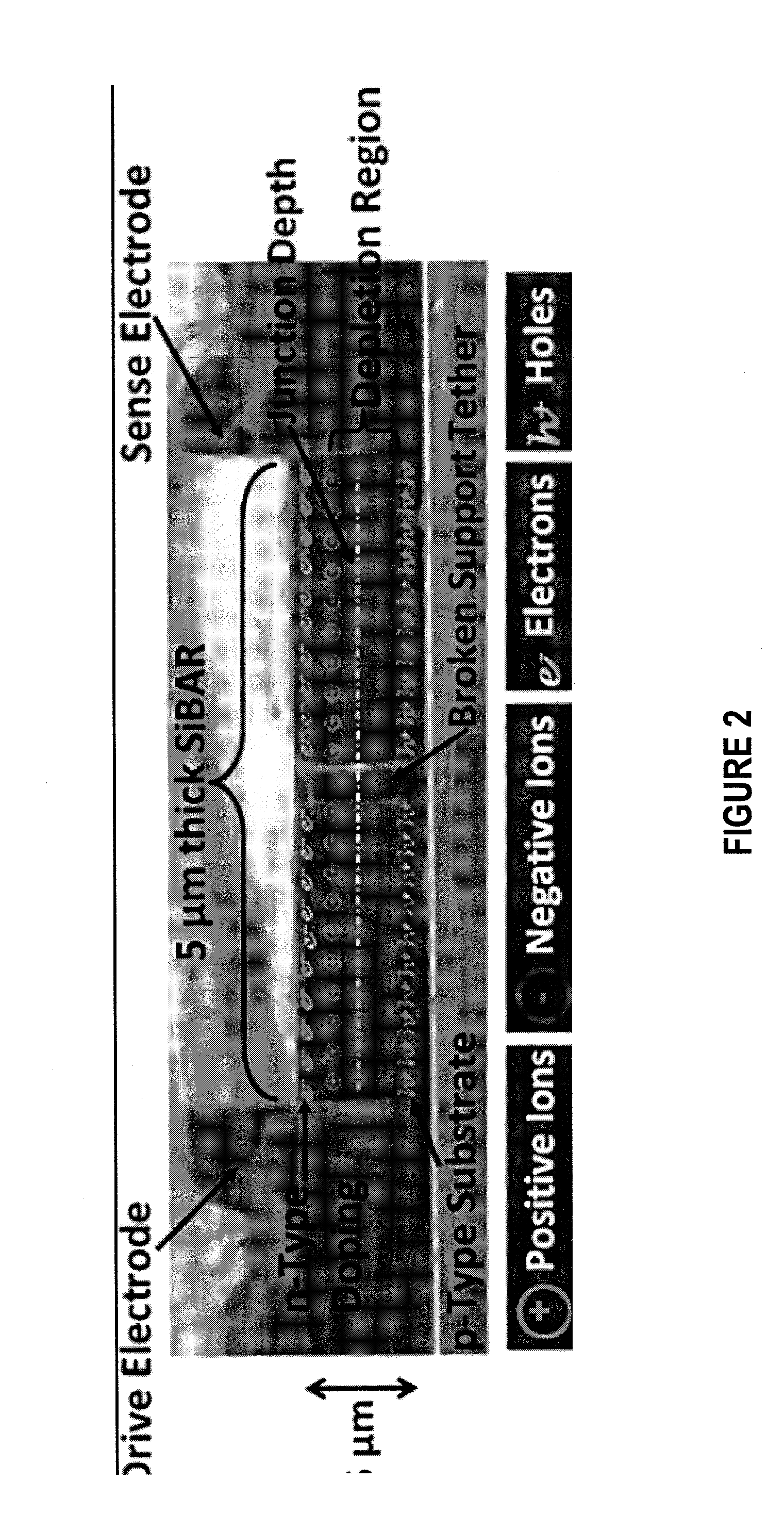
[0027]Technologies herein are directed towards compensating the temperature coefficient of silicon micromechanical resonators without compromising on the quality factor of such resonators. To achieve temperature compensation in silicon micromechanical resonators, the flow of free charge carriers in response to the propagation of acoustic waves in a silicon micromechanical resonator needs to be minimized. The flow of free charge carriers can be minimized by degenerate doping of the silicon micromechanical resonator or by lightly doping the silicon micromechanical resonator to create a pn-junction based free charge carrier depletion region.

[0028]The present disclosure will be more completely understood through the following description, which should be read in conjunction with the drawings. In this description, like numbers refer to similar elements within various embodiments of the present disclosure. Within this description, the claims will be explained with respect to embodiments. ...


PUM


Abstract

A semiconductor resonator has a substrate with a thickness extending between a first end and a second end and a pn-junction along the thickness of the substrate forming a free charge carrier depletion region. In another embodiment, a semiconductor resonator has a substrate with a crystal lattice doped at degenerate levels such that the flow of free charge carriers can be minimized. A method of compensating a temperature coefficient of a semiconductor resonator by creating a pn-junction based free charge carrier depletion region within a thickness of a substrate of the resonator is also disclosed.

Description

STATEMENT REGARDING FEDERALLY SPONSORED RESEARCH OR DEVELOPMENT[0001]This invention was made partially with U.S. Government support from National Science Foundation under grant ECS-0348286. The U.S. Government may have certain rights in the invention.FIELD OF THE INVENTION[0002]The present disclosure relates to silicon micromechanical resonators, and, more specifically, to techniques for reducing the temperature coefficient of frequency for silicon micromechanical resonators.BACKGROUND OF THE INVENTION[0003]The uncompensated temperature coefficient of frequency (TCF) for a native silicon resonator is on the order of −30 ppm / ° C., which is far greater than that of quartz resonators. To achieve stable low-phase-noise frequency references, the TCF needs to be compensated without compromising on the quality factor (Q) of the resonator. Circuit-based compensation techniques add to the power budget whereas depositing compensating materials with positive TCF on silicon is impractical on ce...

Claims


Application Information

Patent Timeline
IPC IPC(8): H01L41/04
CPCH03H3/0076H03H2009/02496H03H9/2463B81B3/0081B81C2201/0171H03H9/02448H03H2009/2415
Inventor AYAZI, FARROKHSAMARAO, ASHWIN
Owner GEORGIA TECH RES CORP
Learn More