Displacement detecting device, scale calibrating method and scale calibrating program

Active Publication Date: 2013-04-25
MITUTOYO CORP
View PDF4 Cites 2 Cited by
  • Summary
  • Abstract
  • Description
  • Claims
  • Application Information

AI Technical Summary

Benefits of technology

The invention is a device and method for accurately calibrating measurement errors on scales. The device is easy and inexpensive to make and uses a self-calibration curve with finer graduations to correct measurement errors. This allows for accurate calibration of scales without the need for a laser interferometer or reference scale. The technical effect of the invention is to provide a reliable and affordable tool for measuring and calibrating scales.

Problems solved by technology

Generally, measurement error of a displacement measuring device such as an encoder is evaluated before shipment.
However, the scale of the encoder may be distorted according to the material and length of the scale and the fixing method when the scale of the encoder is attached to an application such as a machine tool, a measuring device, etc.
In some cases, non-negligible level measurement error in regard to a required specification may be caused by the generated distortion of the scale so that reliability of error data evaluated in advance will be spoiled.
It is however undesirable that a burden is imposed on the user in consideration of the labor for setting up the displacement sensor and the price of the highly accurate displacement sensor.
For this reason, measurement error having a period not longer than twice as long as the arrangement pitch cannot be restored correctly, so that the frequency of measurement error allowed to be calibrated is limited.
For this reason, narrowing the pitch of arrangement of the sensors is limited.
Moreover, use of a highly accurate displacement sensor such as a laser interferometer or preparation of a reference sensor or the like is not desirable because configuration becomes uselessly expensive.
When measurement error of a non-negligible level is caused by distortion of the scale at the time of mounting or the like, it may be necessary to set up the reference displacement sensor again and a lot of cost and labor is still required.

Method used


Image

  • Displacement detecting device, scale calibrating method and scale calibrating program
  • Displacement detecting device, scale calibrating method and scale calibrating program
  • Displacement detecting device, scale calibrating method and scale calibrating program

Examples


Embodiment Construction

[0029]A displacement detecting device, a scale calibrating method and a scale calibrating program according to embodiments of the invention will be described below in detail with reference to the accompanying drawings.

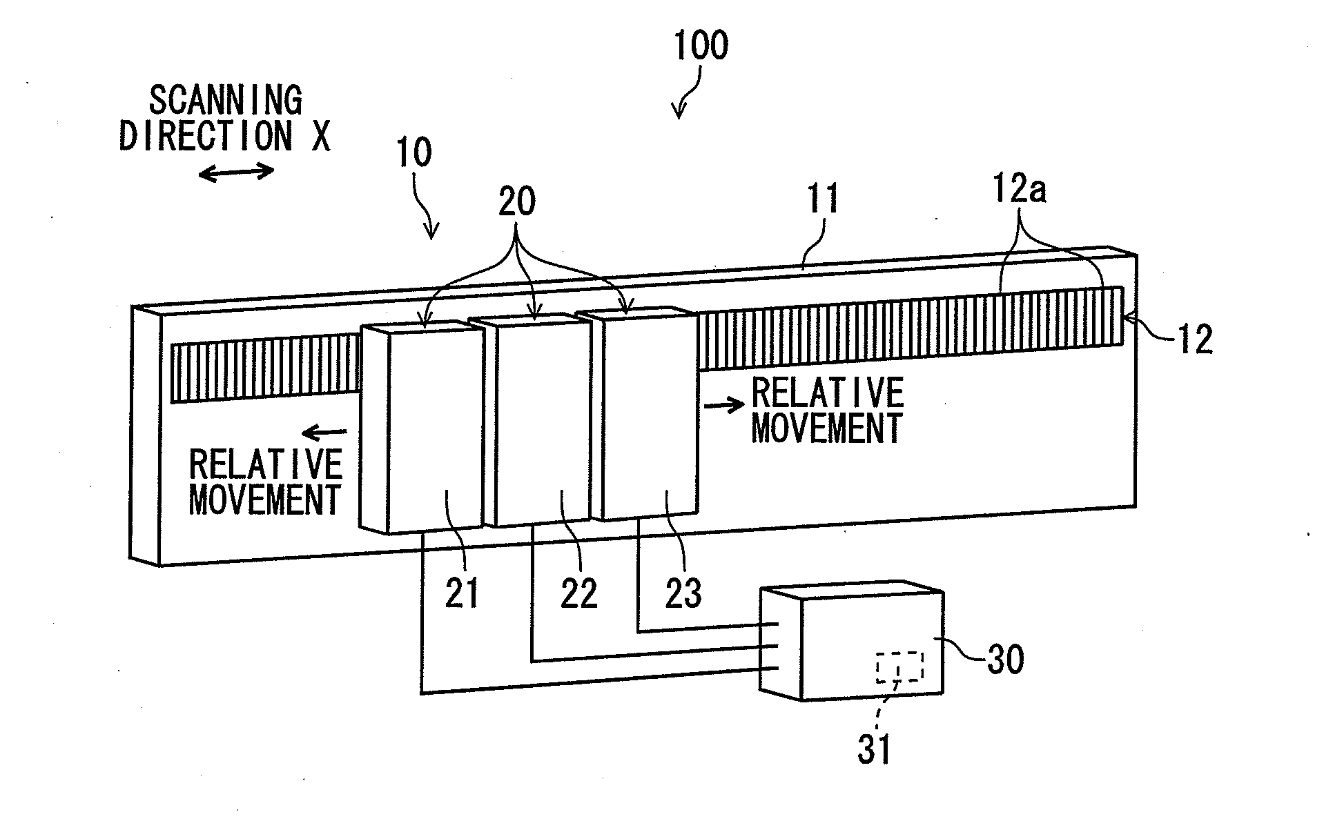
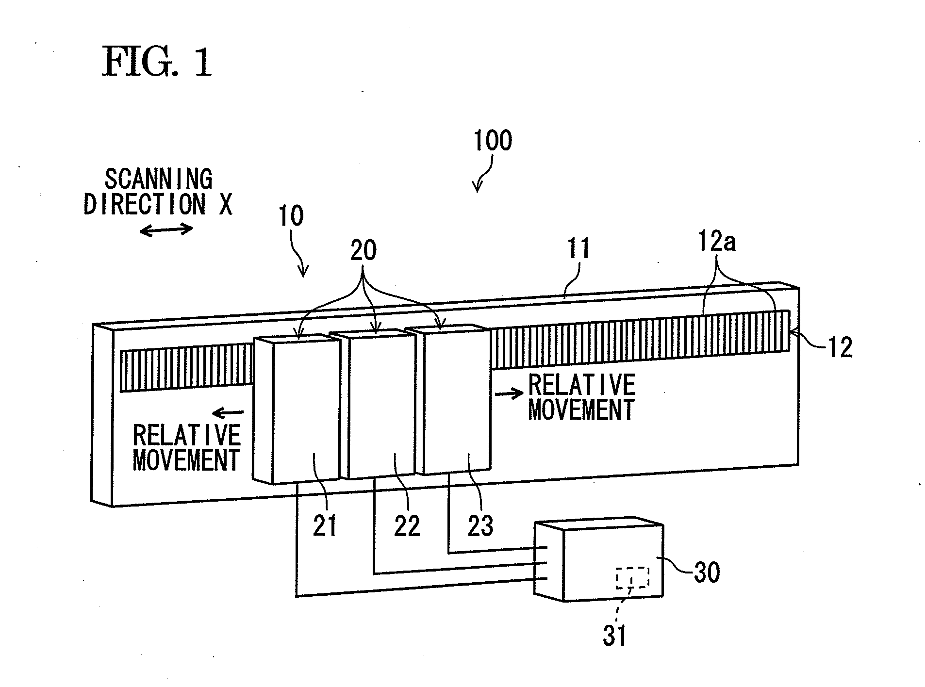
[0030]FIG. 1 is a schematic view showing a configuration of a photoelectric encoder which forms a displacement detecting device according to an embodiment of the invention. As shown in FIG. 1, the photoelectric encoder 100 has a scale 10, a detecting unit 20, and a calculating portion 30. For example, the photoelectric encoder 100 is formed as a reflective type in this embodiment.

[0031]For example, the scale 10 is constituted by a tape scale and has position information for detecting positions of measurement points of detection portions (first to third detection portions) 21, 22 and 23 which form the detecting unit 20. The scale 10 is provided so that light irradiated from the detection portions 21 to 23 of the detecting unit 20 is reflected toward the detection portio...


PUM


Abstract

A displacement detecting device includes: a scale which has an optical lattice; a detecting unit which is disposed so as to be movable in a scanning direction relative to the scale, inclusive of at least a first detection portion, a second detection portion and a third detection portion, arranged in the scanning direction for detecting position information from the optical lattice; and a calculating portion configured to obtain a self-calibration curve on graduations of the scale by specifying positions of the detection portions and calculating measurement error based on the position information detected by the detecting unit, wherein: the detecting unit is provided so that a distance between the first detection portion and the second detection portion and a distance between the second detection portion and the third detection portion are different from each other and do not form an integral multiple.

Description

BACKGROUND[0001]1. Field of the Invention[0002]The present invention relates to a displacement detecting device, a scale calibrating method and a scale calibrating program applied to a linear encoder, a rotary encoder, etc.[0003]2. Description of the Related Art[0004]Generally, measurement error of a displacement measuring device such as an encoder is evaluated before shipment. A highly accurate displacement sensor such as a laser interferometer is used for a reference for error evaluation. The thus obtained error data are shipped in the form of a pre-shipment inspection table together with the encoder so as to be used as important data for warranting performance of the encoder.[0005]However, the scale of the encoder may be distorted according to the material and length of the scale and the fixing method when the scale of the encoder is attached to an application such as a machine tool, a measuring device, etc. In some cases, non-negligible level measurement error in regard to a req...

Claims


Application Information

Patent Timeline
IPC IPC(8): G01D5/347
CPCG01D5/24495G01D5/24452G01D18/001
Inventor KIMURA, AKIHIDE
Owner MITUTOYO CORP
Why Eureka
Try Eureka