
Global clock handler object for hdl environment

a global clock and environment technology, applied in the field of hdls, can solve the problems of complex integrated circuits having a high level of integration, and it is impractical to design at the circuit level or even at the logic gate level

Inactive Publication Date: 2013-04-18
APPLE INC
View PDF12 Cites 1 Cited by
  • Summary
  • Abstract
  • Description
  • Claims
  • Application Information

AI Technical Summary

Benefits of technology

The patent describes a global clock handler object for use in a hardware description language (HDL) environment. The object generates simulated clock signals for different functional blocks of an integrated circuit design. It assigns each simulated clock signal to a unique thread and manages them for the duration of the simulation. The object is a singleton object and is responsible for generating and controlling all the simulated clock signals during the simulation process. This allows for easier and more efficient simulation of integrated circuit designs.

Problems solved by technology

Due in part to the high level of integration achievable with modern fabrication techniques, integrated circuit designs have become very complex.
Complex integrated circuits having a high level of integration are impractical to design at a circuit level or even at a logic gate level.

Method used


Image

  • Global clock handler object for hdl environment
  • Global clock handler object for hdl environment
  • Global clock handler object for hdl environment

Examples


Embodiment Construction

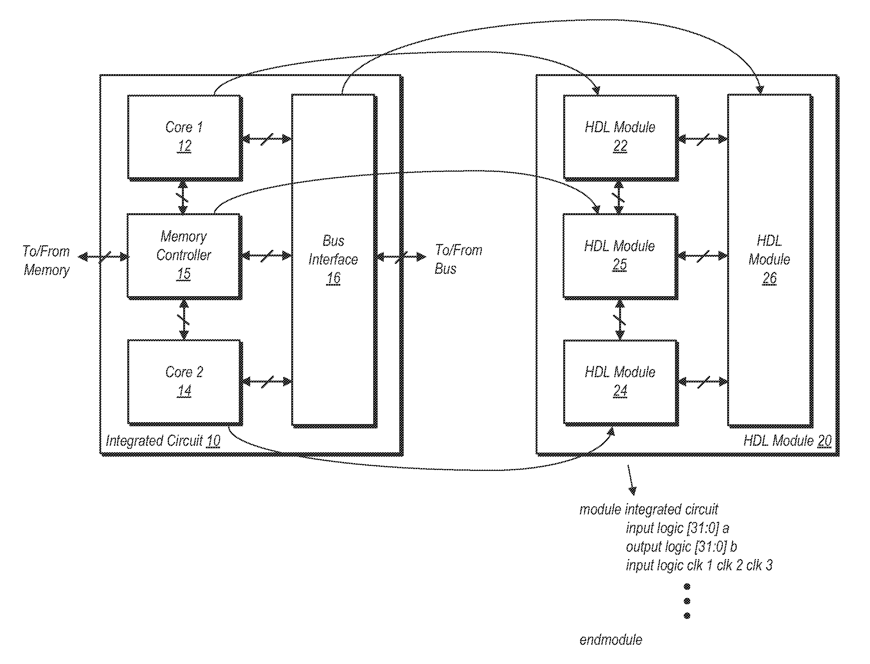
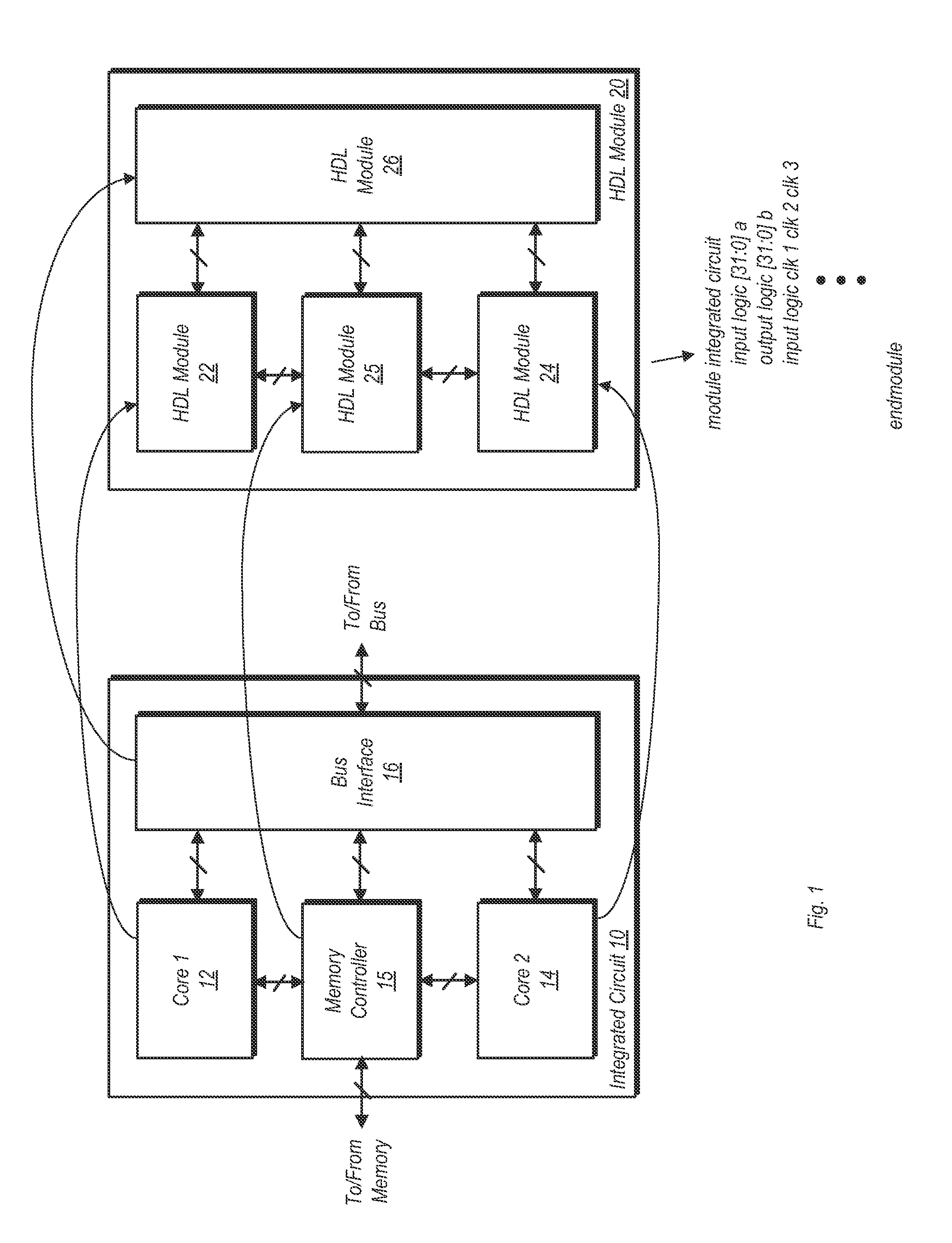
[0016]Turning now to FIG. 1, a block diagram of one embodiment of an integrated circuit design and a corresponding group of hardware description language (HDL) modules corresponding to the design is illustrated. Integrated circuit (IC) 10 in the embodiment shown is a block diagram of a preliminary IC design that includes multiple functional blocks. It is noted that the IC 10 illustrated here is exemplary, and it not intended to be limiting.

[0017]In its proposed design, IC 10 is a multi-core processor having two cores, core 12 and core 14. In one embodiment, cores 12 and 14 may be identical to one another. In another embodiment, the cores may be different, e.g., one core may be implemented for general processing while another core is dedicated to graphics processing. IC 10 further includes a memory controller 15 coupled to both cores. In the final implementation, memory controller 15 is to be configured for providing an interface to a system memory. IC 10 also includes a bus interfac...


PUM


Abstract

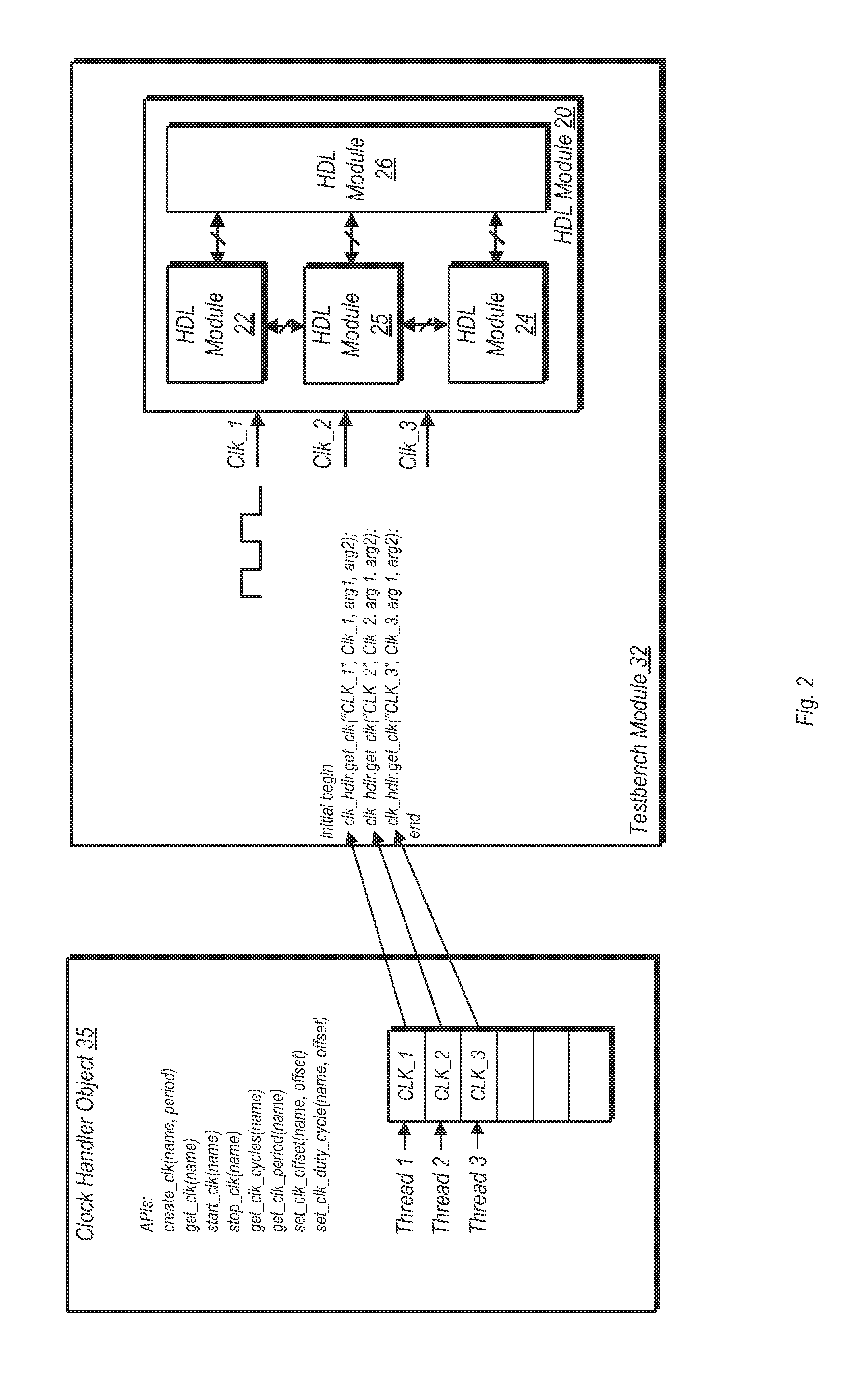
A global clock handler module for use in a hardware description language (HDL) environment is disclosed. An HDL module may include one or more clock statements. When a computer system executes the clock statements, a clock handler object may be called. The clock handler object may generate simulated clock signals for one or more simulated functional blocks of an integrated circuit design. Each simulated clock may be assigned to a separate and unique thread. The clock handler object may be a singleton object configured to manage each simulated clock signal for an integrated circuit design. Generation and control of each simulated clock signal may be performed by the clock handler object in a dynamic array. The dynamic array may include elements specifying parameters for each of the simulated clock signals.

Description

BACKGROUND[0001]1. Field of the Invention[0002]This invention relates to hardware description languages (HDLs), and more particularly, to the generation and control of simulated clock signals in HDL environments.[0003]2. Description of the Related Art[0004]Due in part to the high level of integration achievable with modern fabrication techniques, integrated circuit designs have become very complex. Complex integrated circuits having a high level of integration are impractical to design at a circuit level or even at a logic gate level. Accordingly, to manage complex integrated circuit designs, various hardware description languages (HDLs) have been developed. An HDL allows for a high-level description of an integrated circuit. The description may be in the form of software code executable on a computer system to simulate the integrated circuit design. Additionally, HDL's may be used to write modules known as a testbench, which may be used to test other modules that describe specific ...

Claims


Application Information

Patent Timeline
Patent Type & Authority Applications(United States)
IPC IPC(8): G06F17/50
CPCG06F2217/62G06F17/5022G06F30/396G06F30/33G06F9/455G06F9/06G06F30/3308
Inventor YANG, WILLIAM W.FERNANDO, CHAMEERA R.
Owner APPLE INC
Learn More