
Ladder acoustic wave filter device and branching filter

a technology of acoustic wave filter and a branching filter, which is applied in the direction of impedence networks, electrical equipment, and piezoelectric/electrostrictive/magnetostrictive devices, etc., can solve the problems of deterioration of insertion loss in the lower frequency side portion of the pass band and the difficulty of sufficiently suppressing ripples in the middle portion, so as to achieve significant reduction of insertion loss and effectively suppress ripples in the pass band

Active Publication Date: 2013-04-11
MURATA MFG CO LTD
View PDF4 Cites 11 Cited by
  • Summary
  • Abstract
  • Description
  • Claims
  • Application Information

AI Technical Summary

Benefits of technology

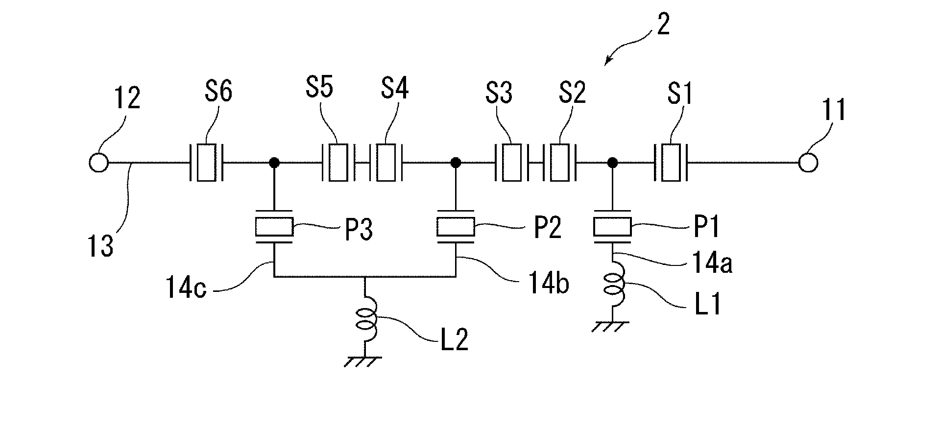
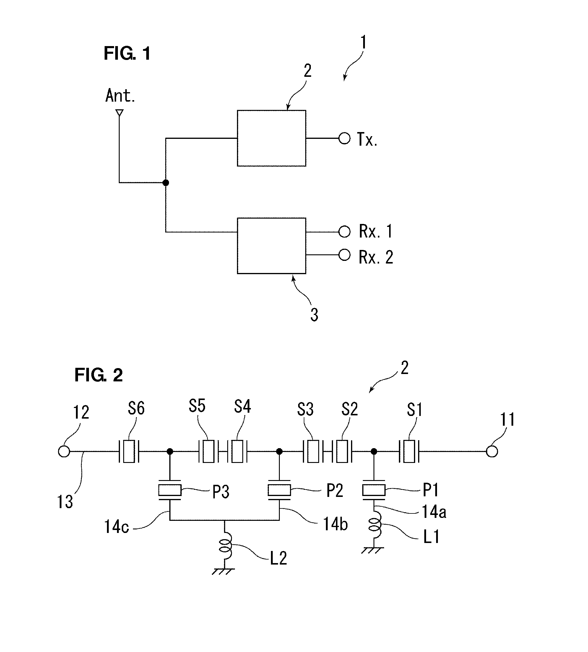
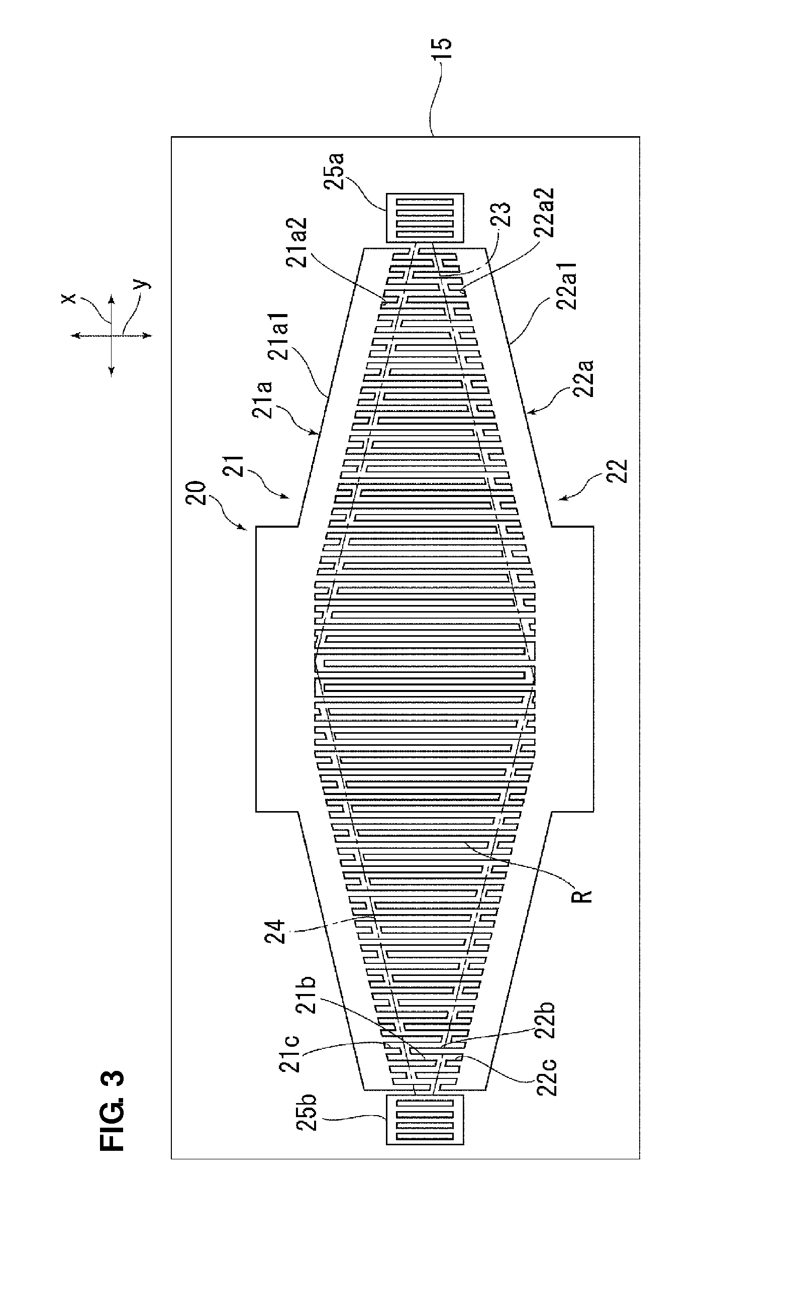
The present invention provides a ladder acoustic wave filter device that has small insertion loss in both low and high frequency side portions of the pass band. The device includes a series-arm-side IDT electrode in all of the plurality of series arm resonators, and busbars of the IDT electrode are configured so that the distance between busbars in the overlap width direction perpendicular to the acoustic wave propagation direction becomes shorter as the overlap width of the electrode fingers becomes smaller. This reduces insertion loss in the high frequency side portion of the pass band and suppresses ripples occurring in the pass band. Additionally, a plurality of parallel arm resonators can be added to reduce insertion loss in the low frequency side portion of the pass band. The ladder acoustic wave filter device can be reduced in size and can be effective in reducing insertion loss and ripples in the pass band.

Problems solved by technology

However, there is a problem in that it is difficult to sufficiently suppress ripples in the middle portion of the pass band.
Moreover, there is a problem in that insertion loss in the lower frequency side portion of the pass band deteriorates.

Method used


Image

  • Ladder acoustic wave filter device and branching filter
  • Ladder acoustic wave filter device and branching filter
  • Ladder acoustic wave filter device and branching filter

Examples


Embodiment Construction

[0031]Preferred embodiments of the present invention will be described below with regard to a branching filter 1 as a duplexer shown in FIG. 1. More specifically, the branching filter 1 according to the present preferred embodiment is a duplexer that preferably supports the UTMS-BAND 8 standard with a transmit frequency band of 880 MHz to 915 MHz and a receive frequency band of 925 MHz to 960 MHz, for example. However, the branching filter according to the present invention is not limited to a duplexer. The branching filter according to the present invention may be, for example, a triplexer. Also, the branching filter according to the present invention may be either of a branching filter using surface acoustic waves, and a branching filter using boundary acoustic waves. In this case, an example of the branching filter 1 using surface acoustic waves will be described.

[0032]As shown in FIG. 1, the branching filter 1 includes a transmitting filter device 2 and a receiving filter device...


PUM


Abstract

A ladder acoustic wave filter device is constructed such that ripples in the pass band are suppressed, and insertion loss is small in both of a high frequency side portion and a low frequency side portion of the pass band. Apodization weighting is applied to a series-arm-side IDT electrode. Busbars of the series-arm-side IDT electrode are configured so that in an acoustic wave propagation direction, a distance in an overlap width direction between the busbars becomes shorter as the overlap width of electrode fingers becomes smaller. Each of a pair of comb-shaped electrodes of a parallel-arm-side IDT electrode further includes a plurality of dummy electrodes that extend from a busbar and are opposed to electrode fingers of the other comb-shaped electrode in the overlap width direction. The parallel-arm-side IDT electrode is a normal IDT electrode in which the overlap width is constant.

Description

BACKGROUND OF THE INVENTION[0001]1. Field of the Invention[0002]The present invention relates to a ladder acoustic wave filter device, and a branching filter including the ladder acoustic wave filter device.[0003]2. Description of the Related Art[0004]In related art, as filter devices for use in communication equipment such as a mobile telephone, acoustic wave filter devices using acoustic waves are used. Acoustic wave filter devices include a longitudinally coupled resonator-type acoustic wave filter device, a ladder acoustic filter device, and so on. For example, a longitudinally coupled resonator-type acoustic wave filter device is preferably used as a receiving filter device in communication equipment which is required to be of a balanced type. On the other hand, a ladder acoustic wave filter device is preferably used as a transmitting filter device that is required to have high electric power handling capability.[0005]For example, according to Japanese Unexamined Patent Applica...

Claims


Application Information

Patent Timeline
Patent Type & Authority Applications(United States)
IPC IPC(8): H03H9/64
CPCH03H9/1452H03H9/64H03H9/6483H03H9/14573
Inventor TAKATA, TOSHIAKI
Owner MURATA MFG CO LTD
Learn More