
Fuel battery system

a fuel battery and power generation system technology, applied in the direction of fuel cells, reactant parameters control, electrical apparatus, etc., can solve the problems of electrode degradation and the efficiency of the fuel battery system, and achieve the effect of short tim

Inactive Publication Date: 2013-04-04
HITACHI LTD
View PDF3 Cites 4 Cited by
  • Summary
  • Abstract
  • Description
  • Claims
  • Application Information

AI Technical Summary

Benefits of technology

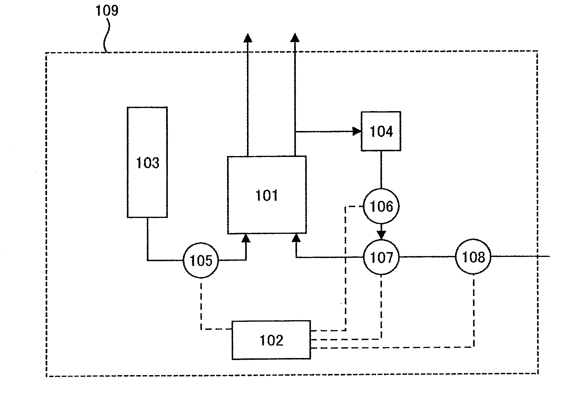
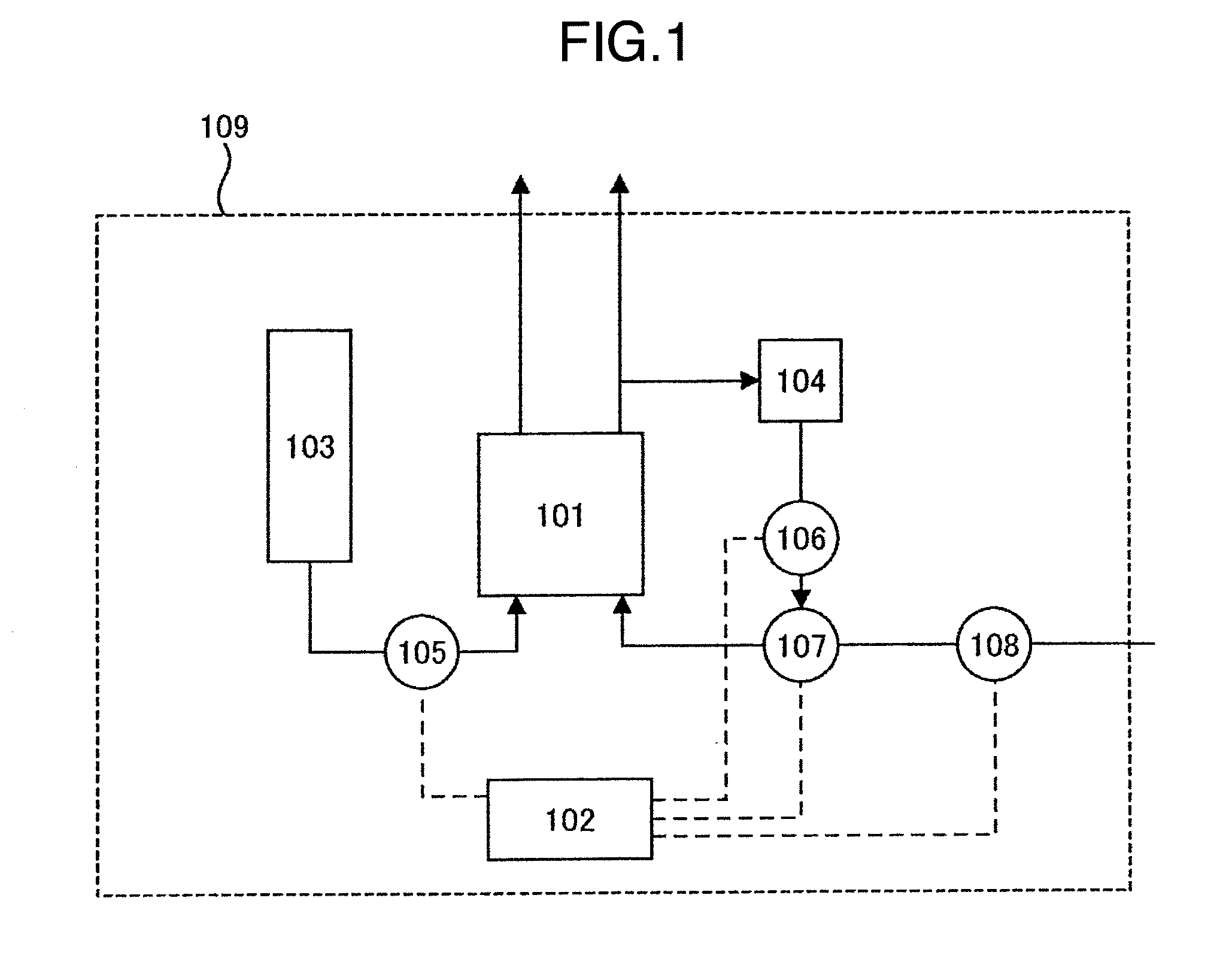
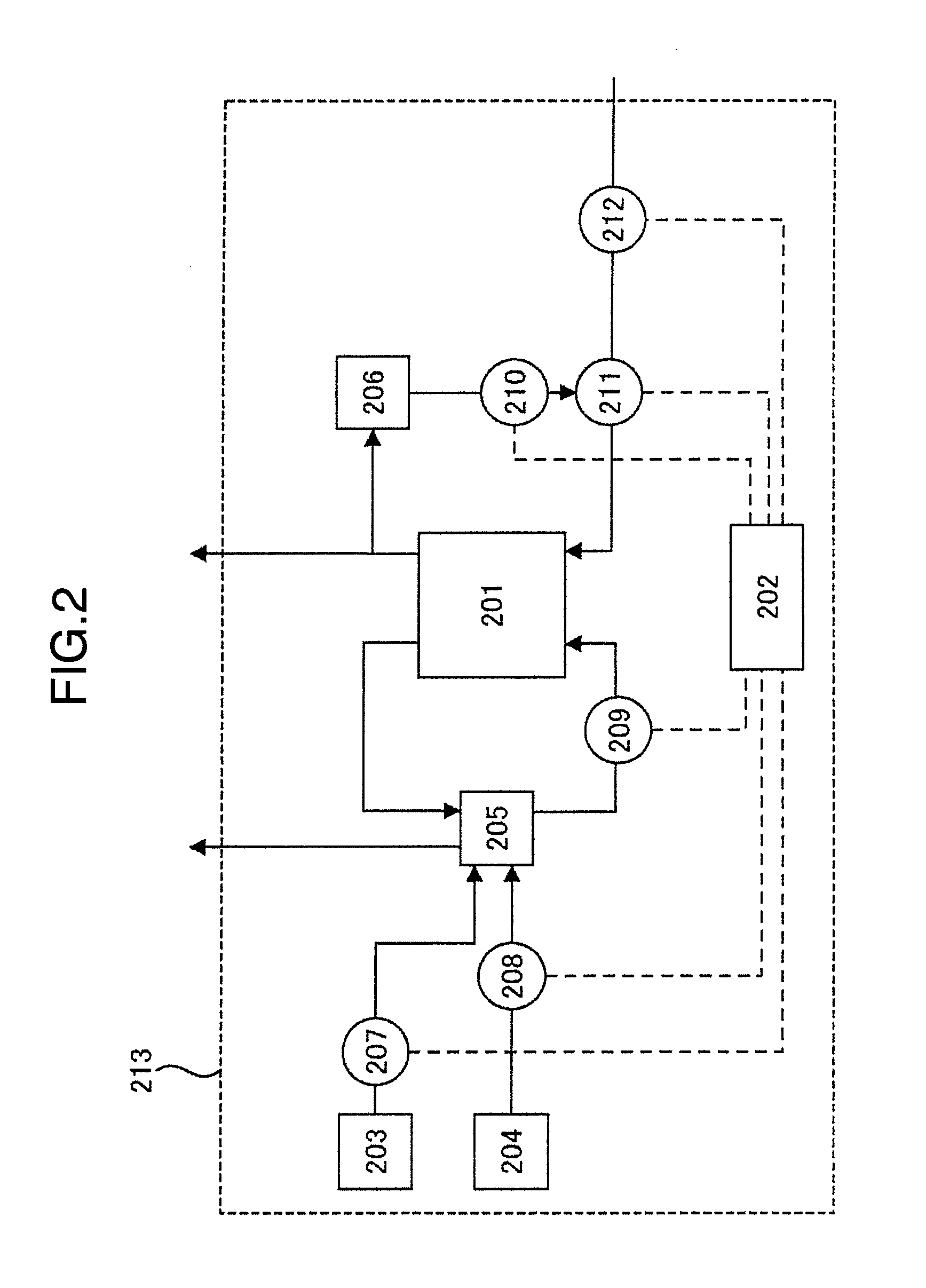
The present invention provides an alkaline fuel battery system that prevents the neutralization of the anion-exchange electrolyte near the cathode when power generation stops, and can start in a short period of time.

Problems solved by technology

However, the method of applying the voltage needs to supply an electric power, which results in a decrease of the efficiency of the fuel battery system.
In addition, the degradation of the electrode progresses due to the application of the voltage of 1.5 V or more.

Method used


Image

  • Fuel battery system
  • Fuel battery system
  • Fuel battery system

Examples


embodiment 1

[0041]A membrane / electrode assembly was produced by applying a slurry which was prepared by mixing a catalyst that is platinum supported by carbon, an anion-exchange electrolyte and a solvent, to both sides of an anion-exchange electrolyte membrane. Next, a fuel battery according to the present embodiment was produced by sandwiching the obtained membrane / electrode assembly with collectors through a carbon cloth which is a diffusion layer. Next, hydrogen with a dew point of 60° C. was supplied to an anode of the fuel battery, air with a dew point of 60° C. was supplied to a cathode, and power generation was performed for 5 minutes at a current density of 50 mA / cm2 and at a battery temperature of 60° C. After that, the power generation was stopped, water was supplied to the cathode, and then the fuel battery system was left in the state for 30 minutes. Incidentally, the supply of hydrogen to the anode was continued. After that, air was supplied to the cathode to extrude the water, and...


PUM

PropertyMeasurementUnit
pHaaaaaaaaaa
voltageaaaaaaaaaa
temperatureaaaaaaaaaa

Abstract

A fuel battery system of the present invention includes: an alkaline fuel battery; a fuel supply device for supplying a fuel to an anode of the fuel battery; an oxidizing agent supply device for supplying an oxidizing agent to a cathode of the fuel battery; a liquid supply device which supplies a liquid to the cathode; a valve which switches between fluids to be supplied to the cathode; and a control device which controls the switching of the valve. The fuel battery system suppresses the neutralization of an anion-exchange electrolyte due to carbon dioxide in the air, by supplying the liquid from the liquid supply device to the cathode and making the cathode in the state of being immersed in the liquid when the fuel battery stops power generation.

Description

BACKGROUND OF THE INVENTION[0001]The present invention relates to a power generation system of a fuel battery.[0002]Along with the progress in recent electronic technology, the amount of information has increased, and the increased information needs to be processed at a higher speed with a higher function. Accordingly, a power source is needed which has a high power density and a high energy density, in other words, which has a long continuous driving period of time.[0003]The necessity for a small generator which does not need charge, that is, a micro-generator which can easily replenish a fuel has increased. Because of such a background, the importance of the fuel battery has been investigated.[0004]The fuel battery is a generator which contains at least a solid or a liquid electrolyte and two electrodes of anode and cathode that induce desired electrochemical reactions, and converts a chemical energy of the fuel directly into an electric energy at high efficiency.[0005]Among such ...

Claims


Application Information

Patent Timeline
Patent Type & Authority Applications(United States)
IPC IPC(8): H01M8/04
CPCH01M8/04955H01M8/0668H01M8/083H01M8/1002H01M8/1011Y02E60/523H01M8/04201H01M8/04223H01M8/04746H01M8/04753H01M2008/1095H01M8/04186H01M8/1007Y02E60/50H01M8/04228H01M8/04225H01M8/04303H01M8/04302
Inventor SUZUKI, SHUICHIONUMA, ATSUHIKOKAWAJI, JUNTAKAMORI, YOSHIYUKIMIZUKAMI, TAKAAKI
Owner HITACHI LTD
Learn More