
Lightung module and illuminant decice having the same

a technology of illuminant and module, which is applied in the direction of instruments, lighting and heating equipment, fibre light guides, etc., can solve the problems of reducing the will of users to use led luminaires, increasing power, and increasing the price of led luminaires. to achieve the effect of enlarge the lighting angle of light passing

Inactive Publication Date: 2013-04-04
CHICONY POWER TECH CO LTD
View PDF10 Cites 36 Cited by
  • Summary
  • Abstract
  • Description
  • Claims
  • Application Information

AI Technical Summary

Benefits of technology

The present invention is a lighting module that aims to expand the lighting angle of light passing through it. This is achieved by directing the path of light through a light guide pillar, which results in a larger lighting angle and better coverage. The invention can be used in ordinary luminaire settings, providing a more complete and even illumination.

Problems solved by technology

However, the power is increased when the number of the LEDs is increased and cannot achieve energy saving, and the price of the LED luminaire is higher than traditional light source.
This reduces the will of users to use LED luminaire.

Method used


Image

  • Lightung module and illuminant decice having the same
  • Lightung module and illuminant decice having the same
  • Lightung module and illuminant decice having the same

Examples


Embodiment Construction

[0034]Reference will now be made in detail to the present embodiments of the invention, examples of which are illustrated in the accompanying drawings. Wherever possible, the same reference numbers are used in the drawings and the description to refer to the same or like parts.

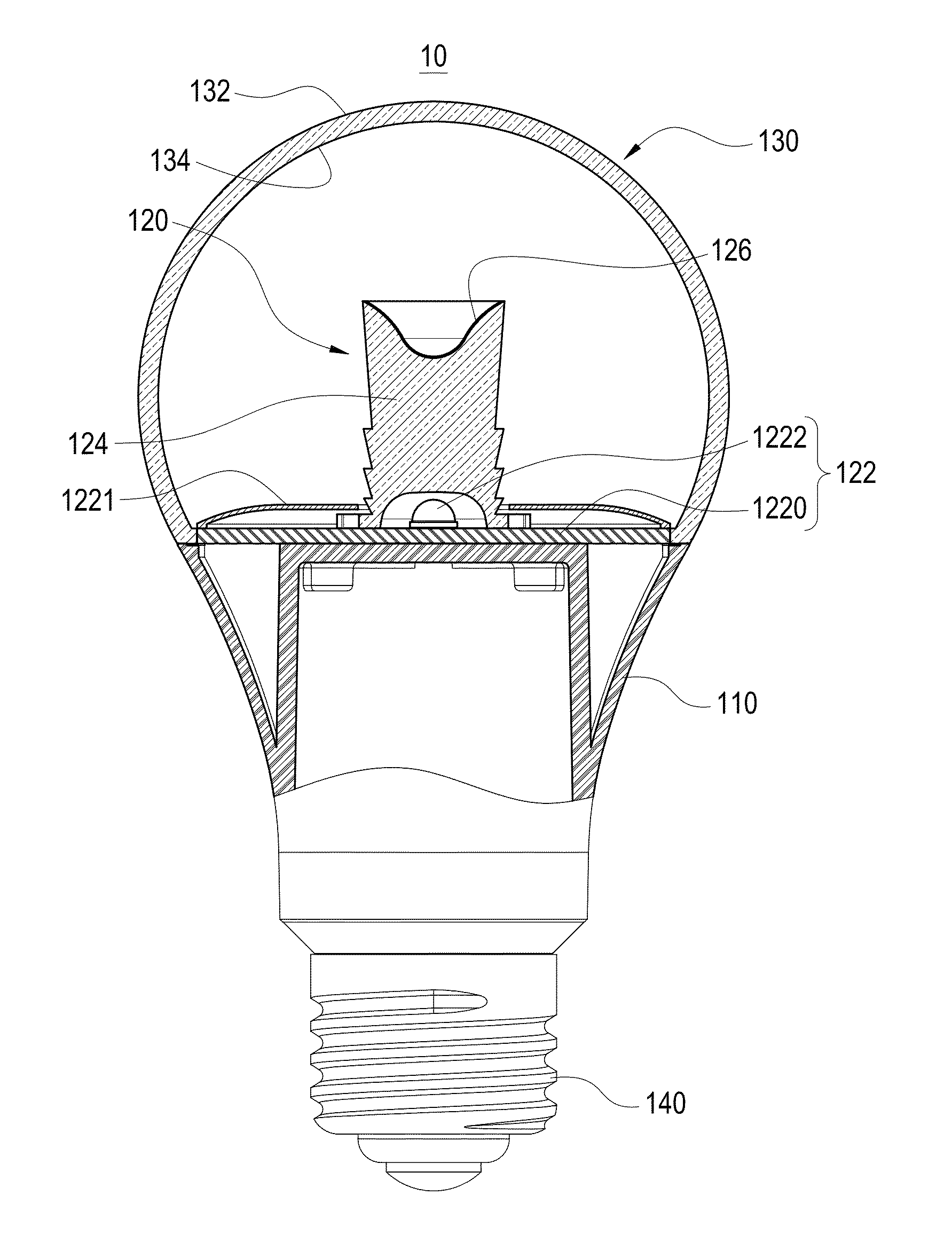
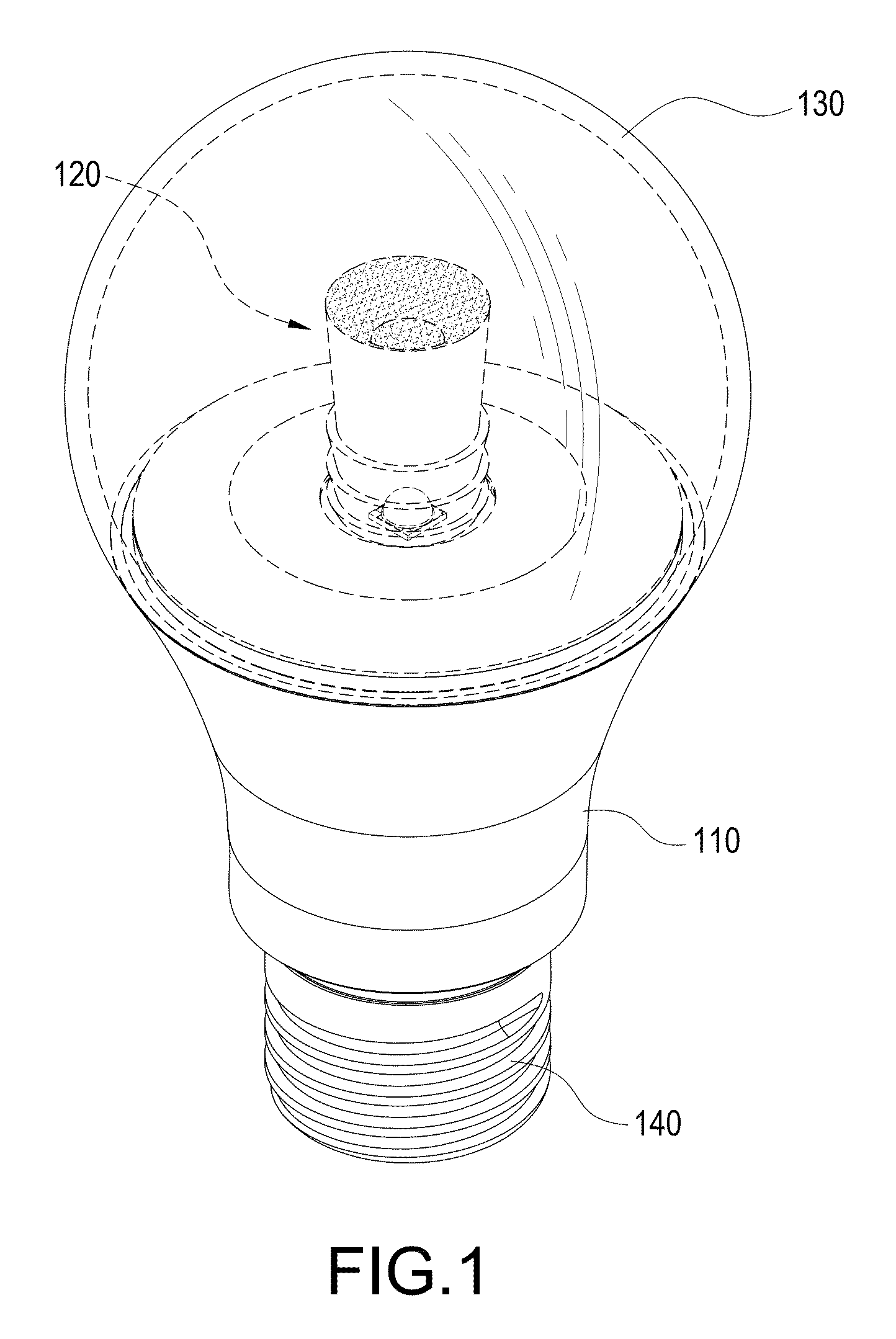
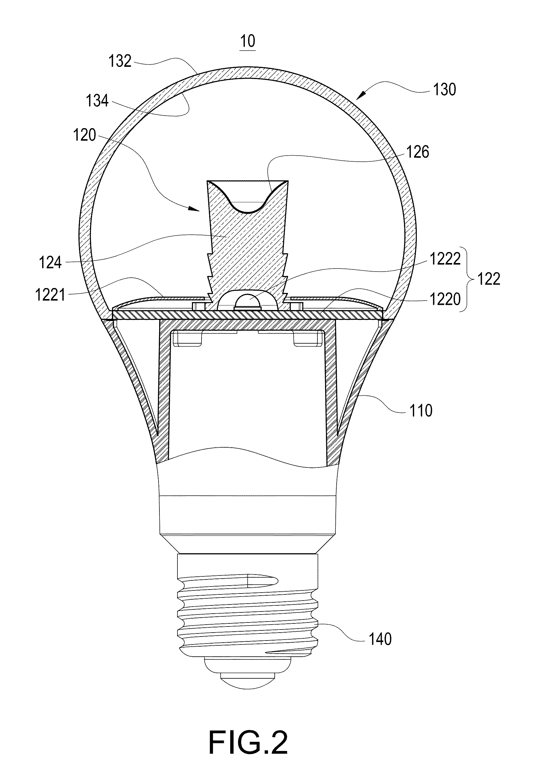
[0035]Reference is made to FIG. 1 and FIG. 2, which are respectively a perspective view and a cross sectional view of an illuminant device according to a first preferred embodiment of the present invention. The illuminant device 10 includes a housing 110, a lighting module 120, a shell 130 and a conductive connector 140.

[0036]The housing 110 is preferably made of metal material or metal material coated with thermal conductivity material thereby to increase the rate of thermal conductivity. Alternatively, the housing 110 may be made of thermal plastic including at least a material with high thermal conductivity coefficient, such as metallic powder, graphite powder or ceramic powder, which can effectively remove...


PUM


Abstract

A lighting module includes an illuminant unit, a light guide pillar and a first reflecting member. The illuminant unit has an optical axis and includes at least a LED. The light guide pillar includes a base and a light guide part, the LED disposed on the base, the light guide pillar is extended from the base along the optical axis and an end of the light guide pillar has a top surface. The top surface is concave toward the base and is continuous. The first reflecting member is disposed on the top surface. Wherein a partial light emitted by the illuminant unit is travelling to the first reflecting member through the light guide pillar, the first reflecting member reflects the partial light such that the partial light emits from the light guide part.

Description

BACKGROUND OF THE INVENTION[0001]1. Field of the Invention[0002]The present invention relates to an illuminant device, and in particular to an illuminant device having light emitting diode.[0003]2. Description of Prior Art[0004]A light emitting diode (LED) is a kind of semiconductor device, which exploits the property of direct-bandgap semiconductor material to convert electric energy into light energy efficiently and has the advantages of long service time, high stability and low power consumption and is developed to replace the traditional non-directivity light tube and incandescent lamp.[0005]The LED is a point-like light source and has high directivity so that the lighting surface of the LED is narrower than that of the traditional light sources, and the luminous intensity of the LED is gradually reduced while the lighting distance is increased, so that the LED is more suitable for providing short-distance and small area lighting fixture, such as table lamp.[0006]In order to app...

Claims


Application Information

Patent Timeline
IPC IPC(8): F21V8/00
CPCG02B6/0003G02B6/001F21K9/135F21K9/52F21V2200/30F21V3/049F21V5/002F21Y2101/02F21K9/56F21K9/232F21K9/61F21K9/64F21Y2115/10F21V5/10
Inventor CHEN, SHIH-PINHUANG, HUAN-HSIANSHAO, CHAN-HUNG
Owner CHICONY POWER TECH CO LTD
Learn More