Layered Solid Sorbents For Carbon Dioxide Capture

a carbon dioxide and solid sorbent technology, applied in the direction of hydrogen sulfide, separation process, other chemical processes, etc., can solve the problems of equipment corrosion, high operating cost, and unwanted foaming of sorbents, and achieve the effect of reducing the number of sorbents

Active Publication Date: 2013-03-28
WEST VIRGINIA UNIVERSITY
View PDF0 Cites 25 Cited by
  • Summary
  • Abstract
  • Description
  • Claims
  • Application Information

AI Technical Summary

Benefits of technology

The present invention provides a solid sorbent that has at least one layer of material that captures gas and at least one layer of material that transfers the gas. The solid sorbent has a porous surface and can be deposited onto a substrate. The first layer of material and the second layer of material can be different materials, and they can be selected from the group of positively charged and negatively charged polymers. The solid sorbent can have a thickness of at least 1 nanometer and can be deposited onto a substrate using a vacuum pressure. The invention also provides a method for preparing the solid sorbent by layer-by-layer nanoassembly of polymers onto a porous support material. The technical effect of this invention is to provide a solid sorbent with improved gas capture and transfer capabilities.

Problems solved by technology

However, the emission of CO2 from fossil fuel combustion has raised great concerns about the relation between anthropogenic CO2 and global warming.
Monoethanolamine (MEA), used as a major aqueous wet scrubbing solvent, has high operating costs due to their heat of sorption plus the sensible and latent heating of the solution.
% in the MEA-based solvent, is a major cause of energy usage above that required for simple desorption of CO2.
However, highly concentrated MEA may lead to equipment-corrosion problems and unwanted foaming.
However, aqueous amine absorption has high operating costs due to their heat of sorption plus the sensible and latent heating of the solution.
Extensive water is required to prevent equipment corrosion and avoid airflow problems, which consequently results in high energy requirements for regeneration.
Meanwhile, loss of amine components due to degradation and evaporation at moderate temperatures is another problem for aqueous amine absorption).

Method used


Image

  • Layered Solid Sorbents For Carbon Dioxide Capture
  • Layered Solid Sorbents For Carbon Dioxide Capture
  • Layered Solid Sorbents For Carbon Dioxide Capture

Examples


examples

[0082]The following examples of preferred embodiments of the present invention set forth the performance of amine-multilayered solid sorbents for CO2 removal and the effect of fabrication variables.

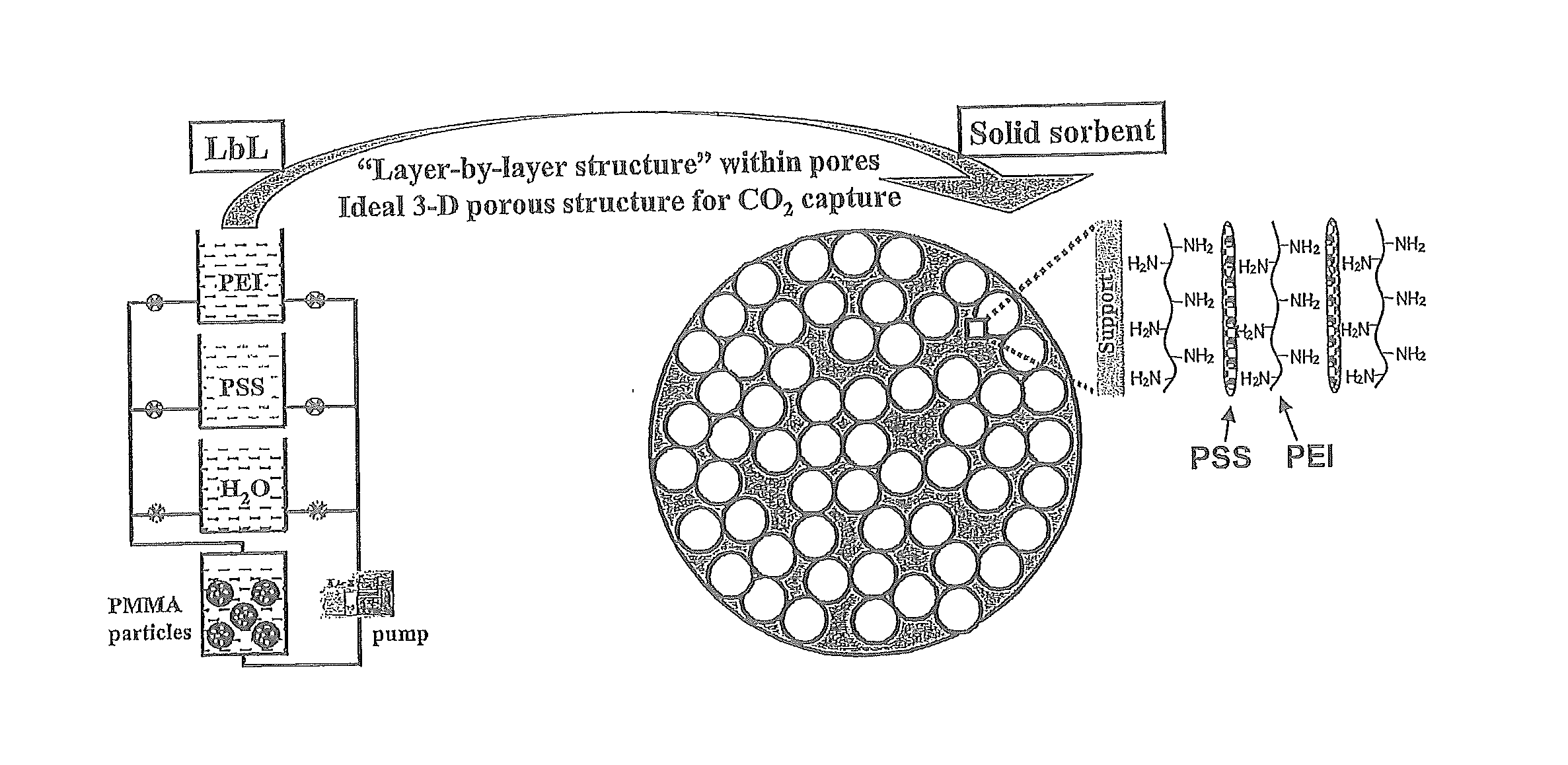
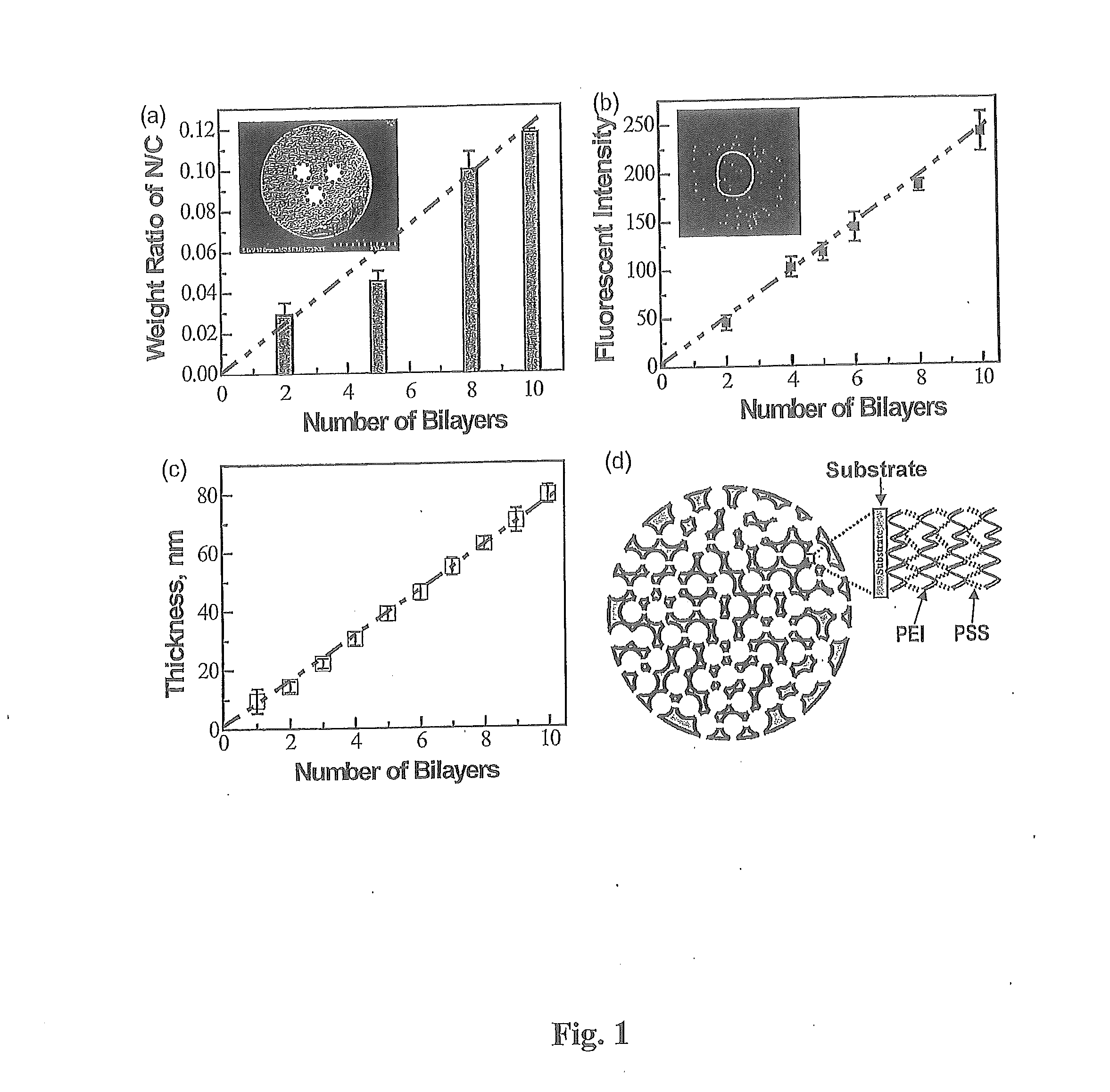
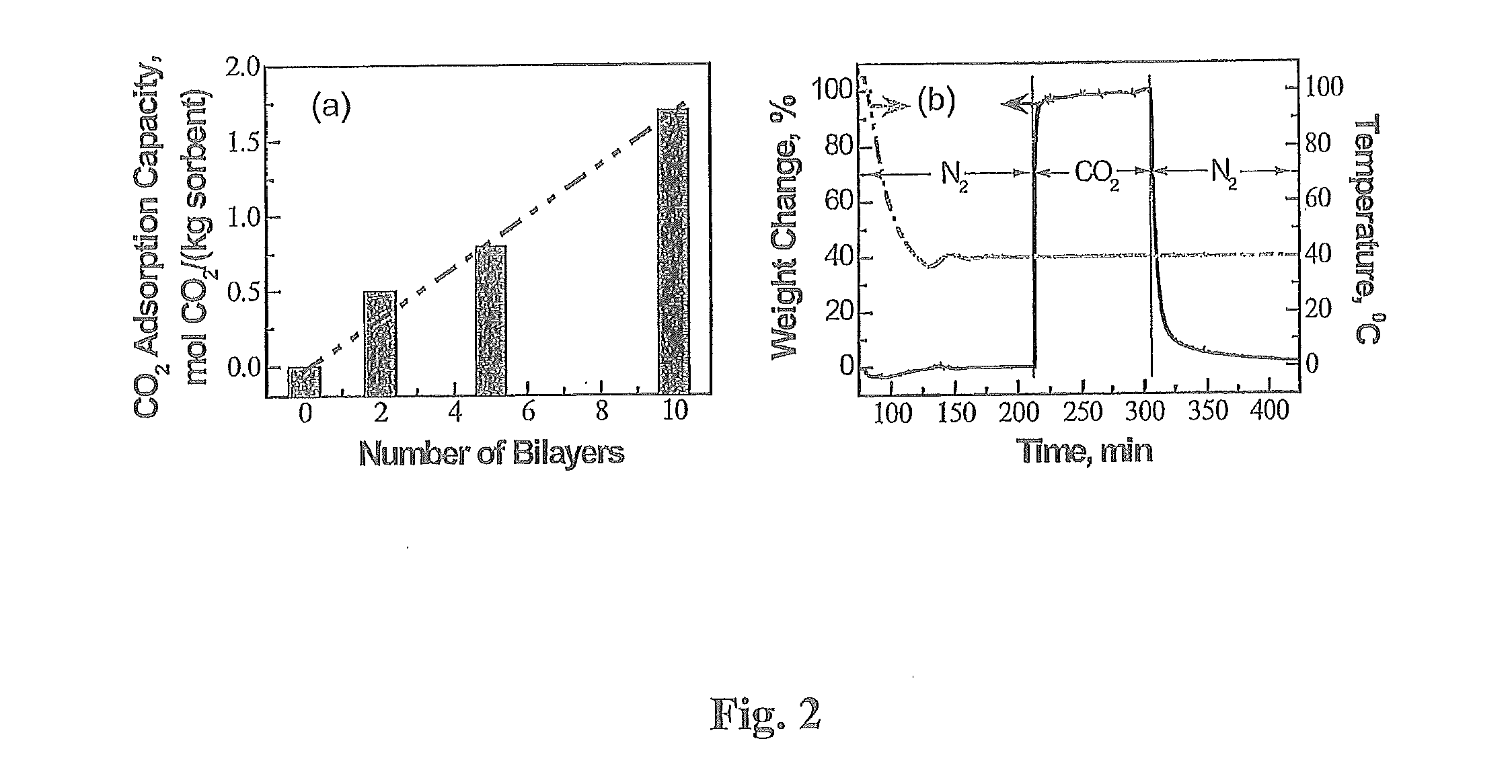
[0083]The emission of fossil fuel carbon dioxide (CO2) to the atmosphere is implicated as the predominant cause of global climate change; therefore, advanced CO2 capture technologies are of the utmost importance. In this study, innovative amine-multilayered sorbents were fabricated using layer-by-layer (LbL) nanoassembly technology via alternate deposition of a CO2-adsorbing amine polymer (e.g. polyethylenimine or PEI) and an oppositely-charged polymer (e.g. polystyrene sulfonate or PSS). We found that the developed sorbents could be used for CO2 capture and that LbL nanoassembly allows us to engineer their CO2 capture performance through the fabrication variables (e.g. deposition polymers, deposition media, and number of bilayers). PEI / PSS was found to be the best polymer combination for...

example no.1

Example No. 1

Preparation of PEI-Multilayered PMMA Sorbents of the Present Invention

[0086]LbL nanoassembly was used to prepare PEI-multilayered sorbents. In addition to employing the from the procedures in the LbL literature, the present invention further applied a vacuum pump to remove air and to run the solutions through the interior pores of sorbent supports (i.e. PMMA particles). Amine-multilayered sorbents were prepared at room temperature. PMMA microparticles were packed in a custom-made deposition chamber. Vacuum was applied first for 30 minutes (30 min) then the following procedures were carried out under 380 ton to prepare PEI-multilayered sorbents in aqueous media as further set forth in FIG. 5: (i) A positively-charged polymer (e.g. PEI or PAH) solution was run through PMMA microparticles for 15 min, then the microparticles were rinsed with deionized water twice for 15 min. (ii) A negatively-charged polymer (e.g. PSS or PAA) solution was run through the PMMA supports follo...

example no.2

Example No. 2

[0097]The chemical structures of PEI, polystyrene sulfonate (PSS), and polymethylmethacrylate (PMMA) are shown in FIG. 13. PEI (Mn=10,000) and PSS (Mn=70,000) were purchased from Sigma Aldrich Co. (St. Louis, Mo.) and individually dissolved in deionized water at a concentration of 10 mg / ml. Porous support, PMMA particles (HP-2MG), was obtained from Sigma Aldrich Co. with the following manufacturer specifications: effective particle size −0.5 mm, pore volume −1.2 ml / g, specific surface area −470 m2 / g, and density −0.29 g / ml. N2 and CO2 of high purity (>99%) were used. The PMMA sheet was purchased from United States Plastic Corp. (Lima, Ohio). Rhodamine B labeled PEI (RhoB-PEI) was synthesized by mixing the solutions in 50 mM phosphate buffer solution at a molar ratio of 1:100 of PEI to rhodamine B, stirring for 2 h at room temperature, and dialyzing in deionized water using a cellulose dialysis sack with a cutoff of 10 kDa for 2 days.

Preparation of PEI / PSS Nano-Layered S...


PUM

PropertyMeasurementUnit
Timeaaaaaaaaaa
Thicknessaaaaaaaaaa
Thicknessaaaaaaaaaa

Abstract

A solid sorbent for the capture and the transport of carbon dioxide gas is provided having at least one first layer of a positively charged material that is polyethylenimine or poly(allylamine hydrochloride), that captures at least a portion of the gas, and at least one second layer of a negatively charged material that is polystyrenesulfonate or poly(acryclic acid), that transports the gas, wherein the second layer of material is in juxtaposition to, attached to, or crosslinked with the first layer for forming at least one bilayer, and a solid substrate support having a porous surface, wherein one or more of the bilayers is / are deposited on the surface of and / or within the solid substrate. A method of preparing and using the solid sorbent is provided.

Description

CROSS-REFERENCE TO RELATED APPLICATION[0001]This utility patent application claims the benefit of co-pending U.S. Provisional Patent Application Ser. No. 61 / 573,746, filed on Sep. 12, 2011. The entire contents of U.S. Provisional Patent application Ser. No. 61 / 573,746 is incorporated by reference into this utility patent application as if fully written herein.STATEMENT REGARDING FEDERALLY SPONSORED RESEARCH[0002]Certain embodiments of this invention were made with Government support in conjunction with the National Energy Technology Laboratory, Pittsburgh, Pa., under RES contract number DE-FE0004000 awarded by the U.S. Department of Energy. The Government may have certain rights in the invention.BACKGROUND OF THE INVENTION[0003]1. Field of the Invention[0004]Nano-layered sorbents for CO2 capture, for the first time, were developed using layer-by-layer nanoassembly. A CO2-adsorbing polymer and a strong polyelectrolyte were alternately immobilized within a porous sorbent substrate. Th...

Claims


Application Information

Patent Timeline
IPC IPC(8): B01J20/28B05D1/04B01J20/26B01D53/02
CPCB01J20/28014Y10T428/24975B05D1/04B01J20/26B01J20/264B01D2253/202B01D2253/25B01D2257/504B01J20/327B01J20/3272B01J20/3289Y02C10/08Y02C10/04B01D53/62B01D53/02Y10T428/24998Y10T428/249953Y10T428/249991Y02C20/40
Inventor LI, BINGYUNJIANG, BINGBINGGRAY, MCMAHAN L.FAUTH, DANIEL J.PENNLINE, HENRY W.RICHARDS, GEORGE A.
Owner WEST VIRGINIA UNIVERSITY
Why Eureka
Try Eureka