Image pickup apparatus and focus detection method
a pickup apparatus and focus detection technology, applied in the field of image pickup apparatus, can solve the problems of deteriorating the focus detection performance of a specific object such as a transverse line, requiring a long calculation time, and a narrow focus detection area to perform good focus detection, and achieve the effect of good accuracy
- Summary
- Abstract
- Description
- Claims
- Application Information
AI Technical Summary
Benefits of technology
Problems solved by technology
Method used
Image
Examples
embodiment 1
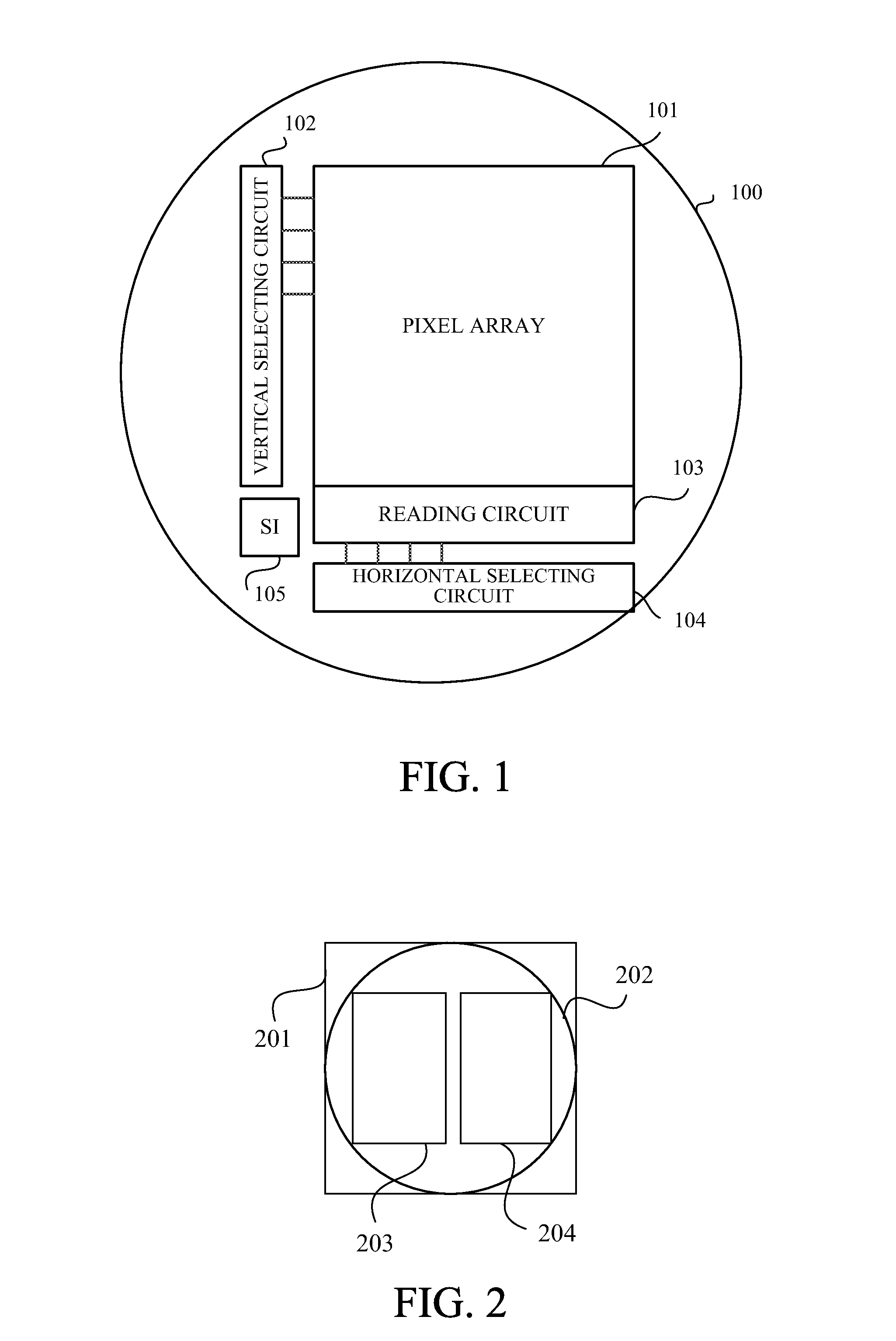
[0028]FIG. 1 shows a configuration of an image sensor (image pickup element) to be used in an image pickup apparatus that is a first embodiment (Embodiment 1) of the present invention. The image sensor 100 is provided with a matrix-like pixel array 101 constituted by plural pixels arranged in a horizontal direction that is a first direction and in a vertical direction that is a second direction orthogonal to the first direction.
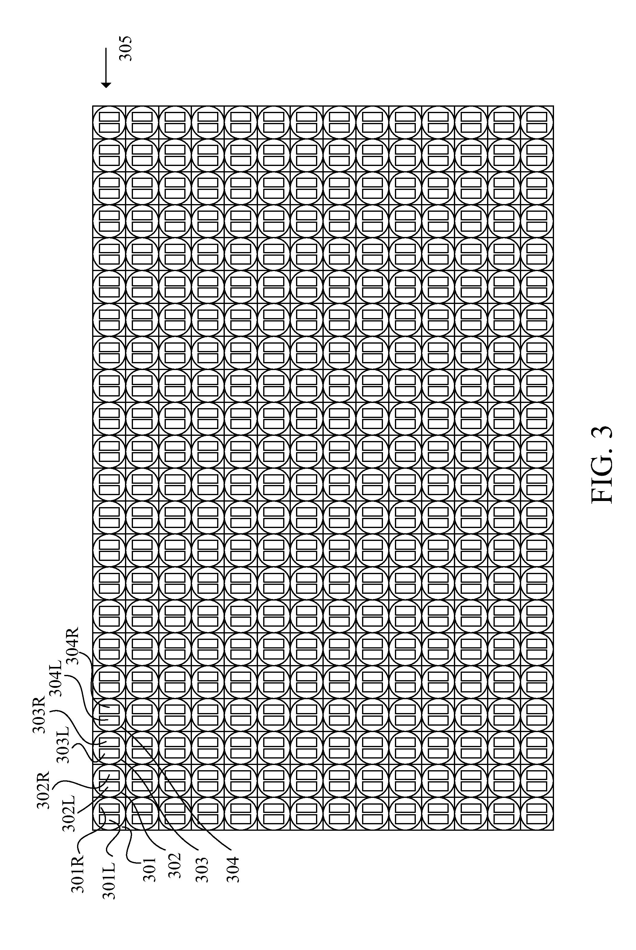
[0029]In the following description, a group of pixels lined in the horizontal direction is referred to as “a pixel line”, and a group of pixels lined in the vertical direction is referred to as “a pixel column”. The pixel array 101 includes plural pixel lines each of which includes plural pixels lined in the horizontal direction and which are arranged in the vertical direction. In other words, the pixel array 101 includes plural pixel columns each of which includes plural pixels lined in the vertical direction and which are arranged in the horizontal directio...
embodiment 2
[0060]Next, description of a second embodiment (Embodiment 2) of the present invention will be made with reference to FIGS. 9A and 9B. FIGS. 9A and 9B show that a substantial size of a focus detection area 603 to be decided depending on a focus detection area 602 including pixel lines p to q in an X (horizontal) direction and pixel columns r to s in a Y (vertical) direction and on a maximum shift amount Imax can be changed according to image capturing conditions.
[0061]The focus detection areas 602 and 603 shown in FIG. 9B are set to be narrower in the horizontal and vertical directions than the focus detection areas 602 and 603 shown in FIG. 9A. The change in sizes of the focus detection areas aims to respond to the fact that the image displacement amount of the A and B images or a size of the A and B images is changed depending on at least one of the image capturing conditions such as a focus state of an image capturing optical system and an F-number thereof.
[0062]For example, sinc...
embodiment 3
[0064]Next, description of a third embodiment (Embodiment 3) of the present invention will be made with reference to FIG. 10. Embodiment 2 has described the case where it is desirable that the change in size of the focus detection area be performed in the horizontal and vertical directions at image capturing of each still image and at image capturing of each frame of a moving image. However, in the vertical direction in which the pixel lines are arranged, the size of the focus detection area may be changed according to various image capturing conditions, without the image capturing (that is, during the image capturing of each still image and during the image capturing of each frame image).
[0065]FIG. 10 shows a state where a substantial focus detection area 603 set in the image sensor 100 is vertically divided into plural areas (each hereinafter referred to as “a divided area”) 1001, 1002 and 1003. Each of the divided areas 1001, 1002 and 1003 includes plural pixel lines and plural p...
PUM
 Abstract
Description
Claims
Application Information
 - R&D
- Intellectual Property
- Life Sciences
- Materials
- Tech Scout
- Unparalleled Data Quality
- Higher Quality Content
- 60% Fewer Hallucinations
Browse by: Latest US Patents, China's latest patents, Technical Efficacy Thesaurus, Application Domain, Technology Topic, Popular Technical Reports.
© 2025 PatSnap. All rights reserved.Legal|Privacy policy|Modern Slavery Act Transparency Statement|Sitemap|About US| Contact US: help@patsnap.com


