
Numerical aperture (NA) controlling unit, variable optical probe including the na controlling unit, and depth scanning method using the na controlling unit

Active Publication Date: 2013-03-21
SAMSUNG ELECTRONICS CO LTD
View PDF9 Cites 54 Cited by
  • Summary
  • Abstract
  • Description
  • Claims
  • Application Information

AI Technical Summary

Benefits of technology

The patent describes an image diagnosis system that can detect images of tissue surfaces at different depths. The system uses a controllable numerical aperture (NA) value to focus light on the tissue surface at a first depth. The system then scans a specific region of the tissue surface at that depth and detects an image. The system then increases the focal length and controls the aperture size to maintain the predetermined NA value. The system then scans a specific region of the tissue surface at a different depth and detects another image. The technical effect is an image diagnosis system that can accurately detect images of tissue surfaces at different depths and provide detailed information on the tissue surface abnormalities.

Problems solved by technology

However, because resolutions of devices for performing such imaging technologies are low, early stage cancer, in which a tumor is small, may not be detected.
However, because resolutions of devices for performing such OCT technologies are lower than the corresponding resolutions of microscopes, OCT technologies may not replace biopsies and histologies, which are actually used in detecting cancer.

Method used


Image

  • Numerical aperture (NA) controlling unit, variable optical probe including the na controlling unit, and depth scanning method using the na controlling unit
  • Numerical aperture (NA) controlling unit, variable optical probe including the na controlling unit, and depth scanning method using the na controlling unit
  • Numerical aperture (NA) controlling unit, variable optical probe including the na controlling unit, and depth scanning method using the na controlling unit

Examples


Embodiment Construction

[0055]Reference will now be made in detail to exemplary embodiments, examples of which are illustrated in the accompanying drawings, wherein like reference numerals refer to like elements throughout. In this regard, the present exemplary embodiments may have different forms and should not be construed as being limited to the descriptions set forth herein. Accordingly, the exemplary embodiments are merely described below, by referring to the figures, to describe aspects of the present disclosure. In the drawings, sizes of elements may be exaggerated for clarity and convenience. As used herein, the term “and / or” includes any and all combinations of one or more of associated listed items. Expressions such as “at least one of”, when preceding a list of elements, modify the entire list of elements and do not modify the individual elements of the list.

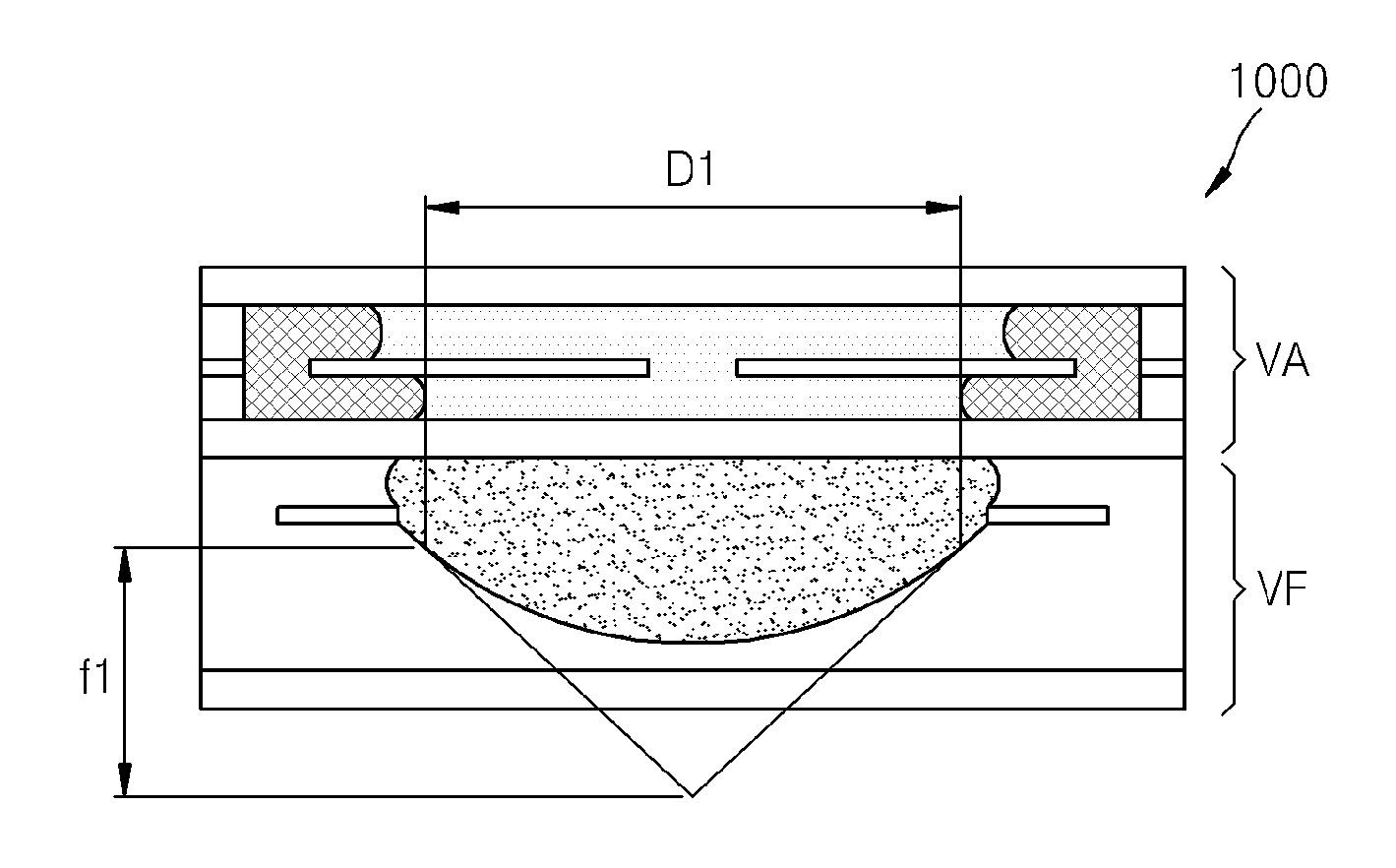
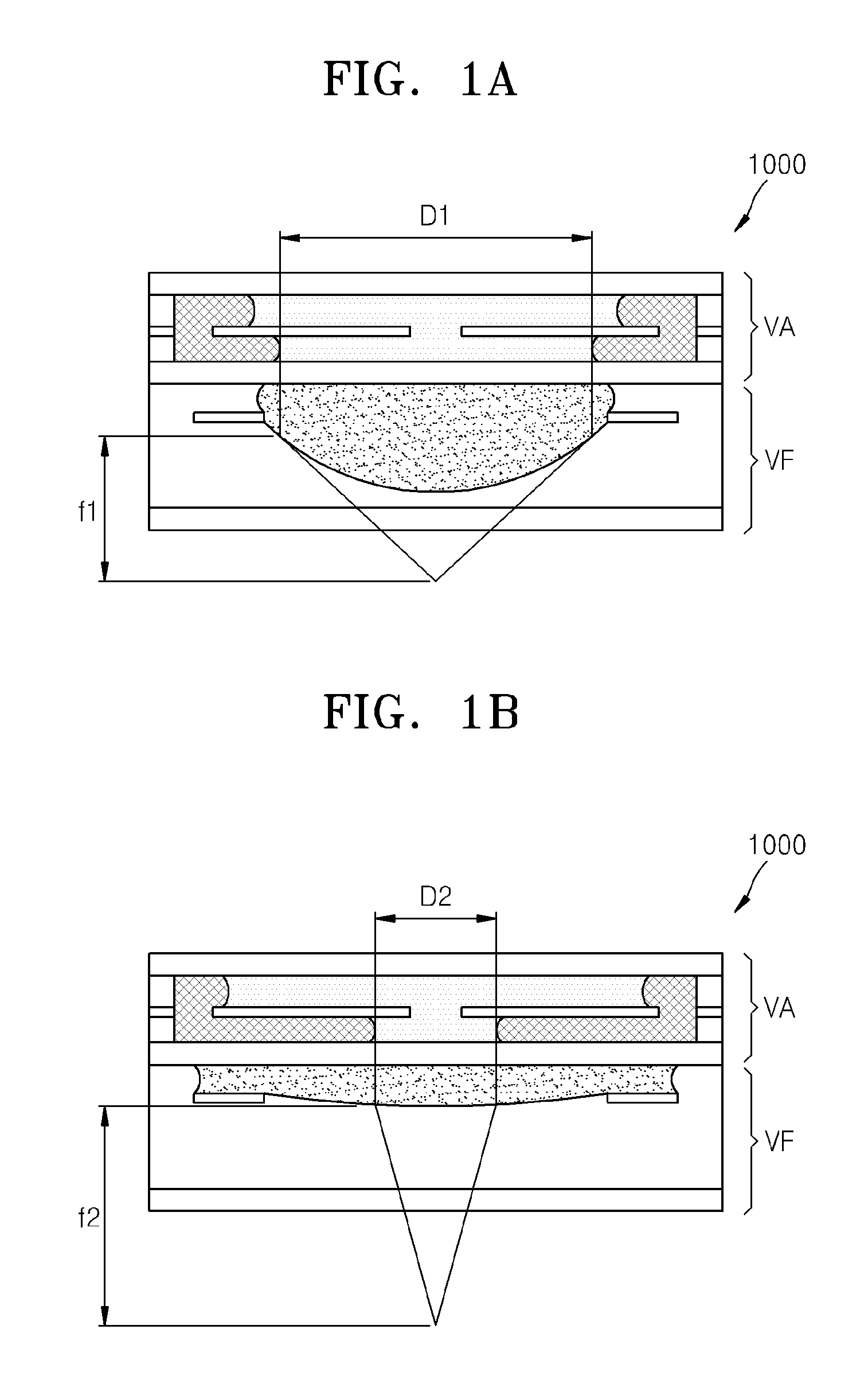
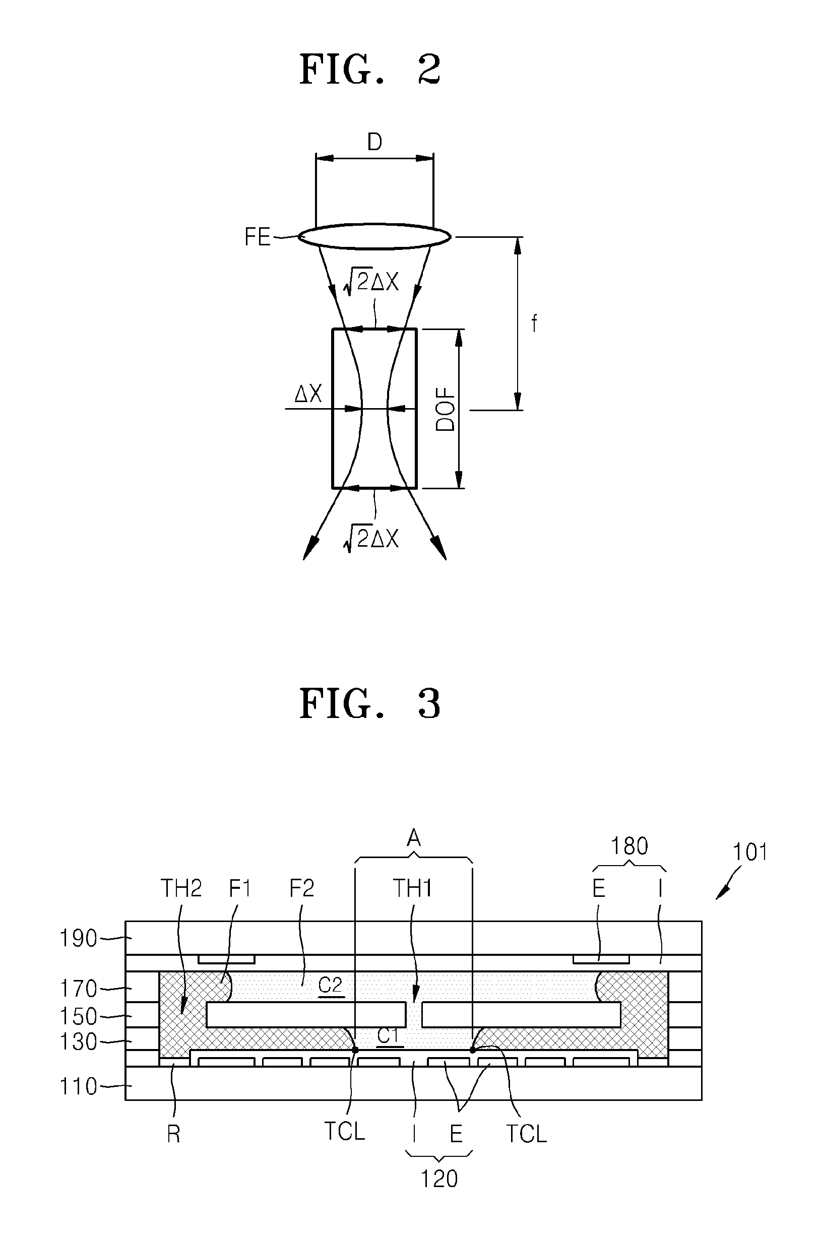
[0056]FIGS. 1A and 1B illustrate a schematic structure of a numerical aperture (NA) controlling unit 1000 having different NA values, accor...


PUM


Abstract

A numerical aperture (NA) controlling unit and a variable optical probe including the same are provided. The NA controlling unit includes: an aperture adjustment unit which controls an aperture through which light is transmitted; and a focus control unit that is disposed in a predetermined position with respect to the aperture adjustment unit, that focuses light transmitted through the aperture, and that has an adjustable focal length. The variable optical probe includes: a light transmission unit; a collimator that collimates light transmitted through the light transmission unit into parallel light; an NA controlling unit that focuses light on a sample to be inspected; and a scanner that varies a path of light transmitted through the light transmission unit such that a predetermined region of the sample is scanned by light that passes through the NA controlling unit.

Description

CROSS-REFERENCE TO RELATED APPLICATIONS[0001]This application claims priority from Korean Patent Application No. 10-2011-0093647, filed on Sep. 16, 2011, in the Korean Intellectual Property Office, the disclosure of which is incorporated herein by reference in its entirety.BACKGROUND[0002]1. Field[0003]Exemplary embodiments described herein relate to numerical aperture (NA) controlling units that control numerical aperture (NA), variable optical probes which include the NA controlling units, and depth scanning methods which use the NA controlling units.[0004]2. Description of the Related Art[0005]The demand for technologies relating to performing precise tomography on lower layers of human skin tissue and the demand for information relating to human skin tissue in the field of medical imaging are increasing. In particular, because many cancers originate in lower cells of the epithelium and are spread into cells of the hypodermis, in which blood vessels exist, if cancer can be detect...

Claims


Application Information

Patent Timeline
IPC IPC(8): G02B26/02G01N21/55G02B26/10G02F1/29G02B3/14G01N21/17G02B7/04G02B21/00G02B26/00G02B26/08G03B9/00
CPCA61B5/0066G01B9/02063G01B11/22G02B3/14A61B5/444G02B5/005G02B21/006G02B26/005G02B26/101G01B9/02091A61B5/06G01B9/02G01N29/24
Inventor CHOI, MIN-SEOGLEE, SEUNG-WANKIM, WOON-BAELEE, EUN-SUNGJUNG, KYU-DONGCHANG, JONG-HYEON
Owner SAMSUNG ELECTRONICS CO LTD
Learn More