
Apparatus comprising a pickup providing multiple beams

a technology of a pickup and a beam, which is applied in the direction of data recording, instruments, disposition/mounting of heads, etc., can solve the problems of reducing the effective size of the light spot used for reading or writing to the optical storage medium, and not allowing reducing the track pitch, so as to reduce distortion and reduce crosstalk signals

Inactive Publication Date: 2013-03-07
THOMSON LICENSING SA
View PDF19 Cites 1 Cited by
  • Summary
  • Abstract
  • Description
  • Claims
  • Application Information

AI Technical Summary

Benefits of technology

The invention is about a device that reduces distortions in a high-frequency signal caused by the structure of adjacent tracks. The device uses advanced signal processing techniques to eliminate or minimize crosstalk signals. The device includes a detector that calculates data streams for the adjacent tracks and a digital filter that processes the data streams. These filters are then used to reduce the distortion signals from the adjacent tracks. The technical effect of the invention is to improve the accuracy and quality of the high-frequency signal.

Problems solved by technology

This is possible by including a nonlinear layer, which is placed above a data layer of the optical storage medium, and which significantly reduces the effective size of a light spot used for reading from or writing to the optical storage medium.
The super-resolution effect allows increasing the resolution of the pickup for reading of the marks on an optical disc, but does not allow reducing the track pitch.

Method used


Image

  • Apparatus comprising a pickup providing multiple beams
  • Apparatus comprising a pickup providing multiple beams
  • Apparatus comprising a pickup providing multiple beams

Examples


Embodiment Construction

[0030]With regard to FIG. 1, the principle of a 3-beam tracking method is explained for an apparatus comprising a pickup with a laser, an objective lens and a detector unit, as known from prior art. The pickup provides a main beam 1 for reading a data signal from a track T2 of an optical disc and two satellite beams 2 and 3 for providing a tracking error signal for a tracking control of the pickup.

[0031]As shown in FIG. 1a in a simplified manner, the optical disc comprises three essentially parallel tracks T1, T2, T3 with pits P, which provide a high frequency (HF) data signal, when read by the pickup. The tracks T1-T3 are each separated from one another by a track pitch TP. The beams 1, 2, 3 moves in a tangential direction for reading the data signal of a respective track, here track T2, in accordance with the rotating speed of the optical disc. The tracking control is performed in radial direction, for keeping the main beam 1 in the centre of the respective pits of track T2.

[0032]...


PUM

PropertyMeasurementUnit
laser wavelengthaaaaaaaaaa
lengthaaaaaaaaaa
lengthaaaaaaaaaa

Abstract

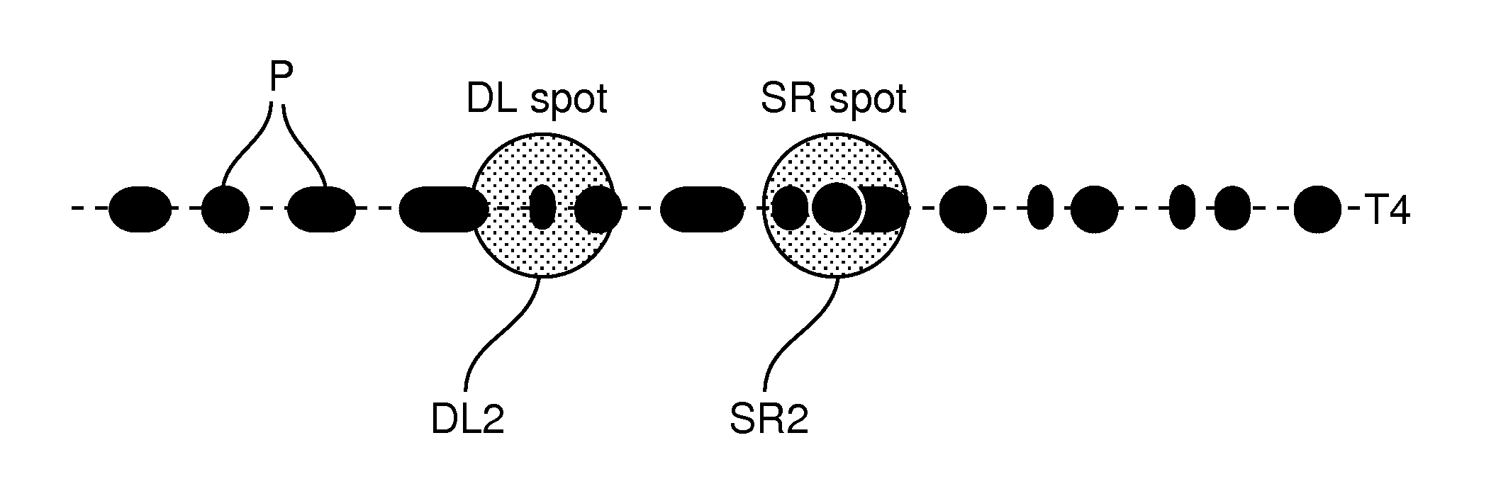
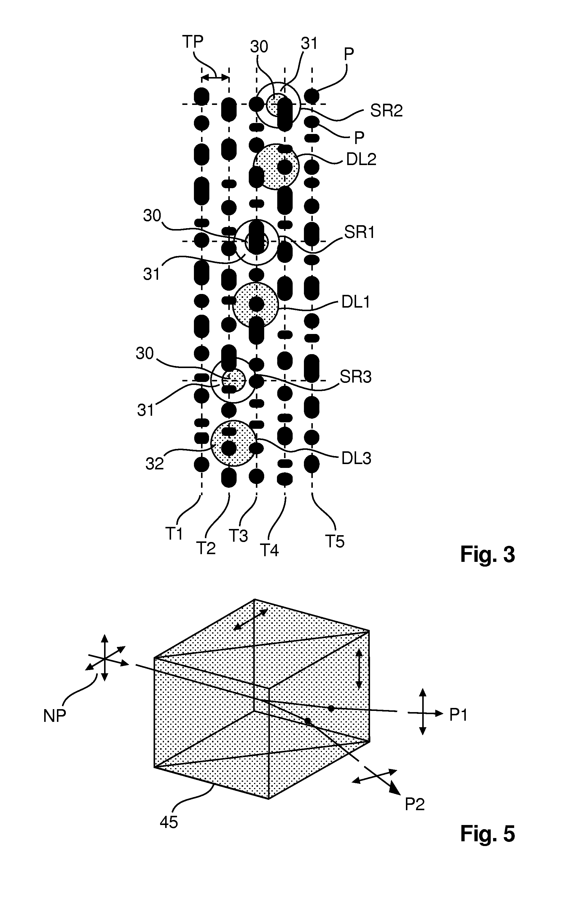
The apparatus includes a pickup for reading data from a super-resolution optical disc, the pickup comprising a laser for generating a main beam, a first and a second satellite beam, the two satellite beams each having a radial offset with regard to the main beam, a third satellite beam following the first satellite beam, having the same radial offset as the first satellite beam, and a fourth satellite beam following the second satellite beam, having the same radial offset as the second satellite beam, for providing a crosstalk correction of the HF data signal. The track pitch between adjacent tracks of the optical disc is particularly below the diffraction limit of the pickup, and the light intensity of each of the first and second satellite beams and of the main beam is sufficient to provide a super-resolution effect on the optical disc and the light intensity of each of the third and fourth satellite beams is not sufficient to provide the super-resolution effect. The track pitch between adjacent tracks of the optical disc is advantageously below the diffraction limit of the pickup.

Description

FIELD OF THE INVENTION[0001]The present invention relates to an apparatus comprising a pickup with a laser and an objective lens for focusing a main beam and several satellite beams onto an optical disc.BACKGROUND OF THE INVENTION[0002]Optical storage media are media in which data are stored in an optically readable manner, for example by means of a pickup comprising a laser for illuminating the optical storage medium and a photo-detector for detecting the reflected light of the laser beam when reading the data. In the meanwhile a large variety of optical storage media are available, which are operated with different laser wavelength, and which have different sizes for providing storage capacities from below one Gigabyte up to about 50 Gigabyte (GB). Digital data are stored in these media along tracks in one or more layers of the media.[0003]The storage medium with the highest data capacity is at present the Blu-Ray disc, which allows to store up to 50 GB on a dual layer disc. Avail...

Claims


Application Information

Patent Timeline
Patent Type & Authority Applications(United States)
IPC IPC(8): G11B7/09G11B7/1353G11B7/1374G11B7/1395G11B7/14
CPCG11B7/0903G11B7/1353G11B7/24079G11B7/14G11B7/1395
Inventor HOELZEMANN, HERBERTKNAPPMANN, STEPHAN
Owner THOMSON LICENSING SA
Learn More