
Radio frequency power amplifier protection system

a protection system and power amplifier technology, applied in amplifiers with semiconductor devices/discharge tubes, gain control, instruments, etc., can solve problems such as damage to power amplifier voltage levels, devices at risk of permanent damage, and imperfect load of transmitter antennas

Active Publication Date: 2013-02-28
SPECTRALUX
View PDF2 Cites 30 Cited by
  • Summary
  • Abstract
  • Description
  • Claims
  • Application Information

AI Technical Summary

Benefits of technology

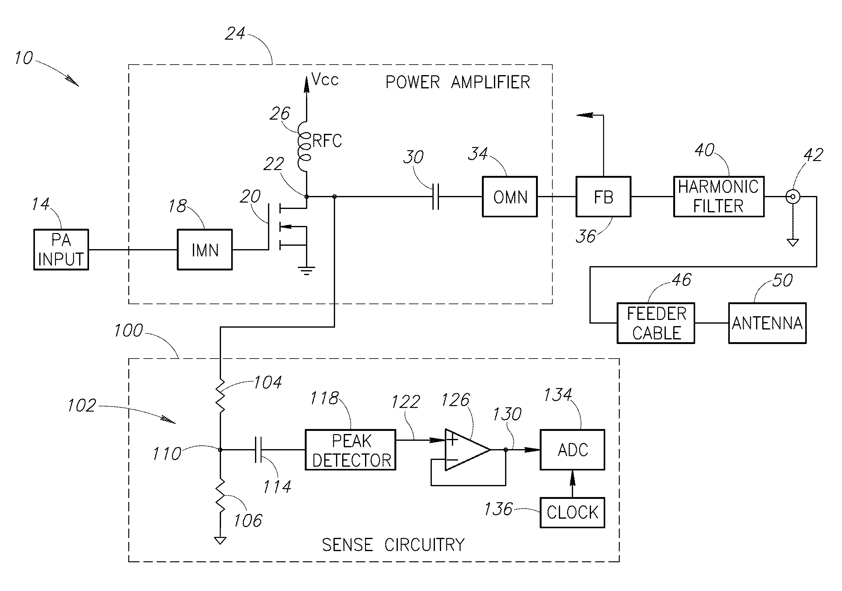
The present invention is directed to protecting RF power amplifiers from damage caused by poor load impedances. The technical effect of the invention is to provide a system and method for protecting RF power amplifiers from damage caused by reflections. The invention uses a load impedance match to minimize the amount of reflected power and prevent damage to the amplifier. The invention also takes into account the variation in signal amplitude in complex modulation schemes to avoid damage caused by peaks in the power.

Problems solved by technology

In practice, transmitter antennas are not a perfect load.
Such devices are at risk of permanent damage due to excessive reflected voltages.
This can cause damaging voltage levels at the power amplifier when, unlike an open-loop condition that would result in a “sag,” the feedback loop forces the power back up and creates excessive voltage at the transistor.

Method used


Image

  • Radio frequency power amplifier protection system
  • Radio frequency power amplifier protection system
  • Radio frequency power amplifier protection system

Examples


Embodiment Construction

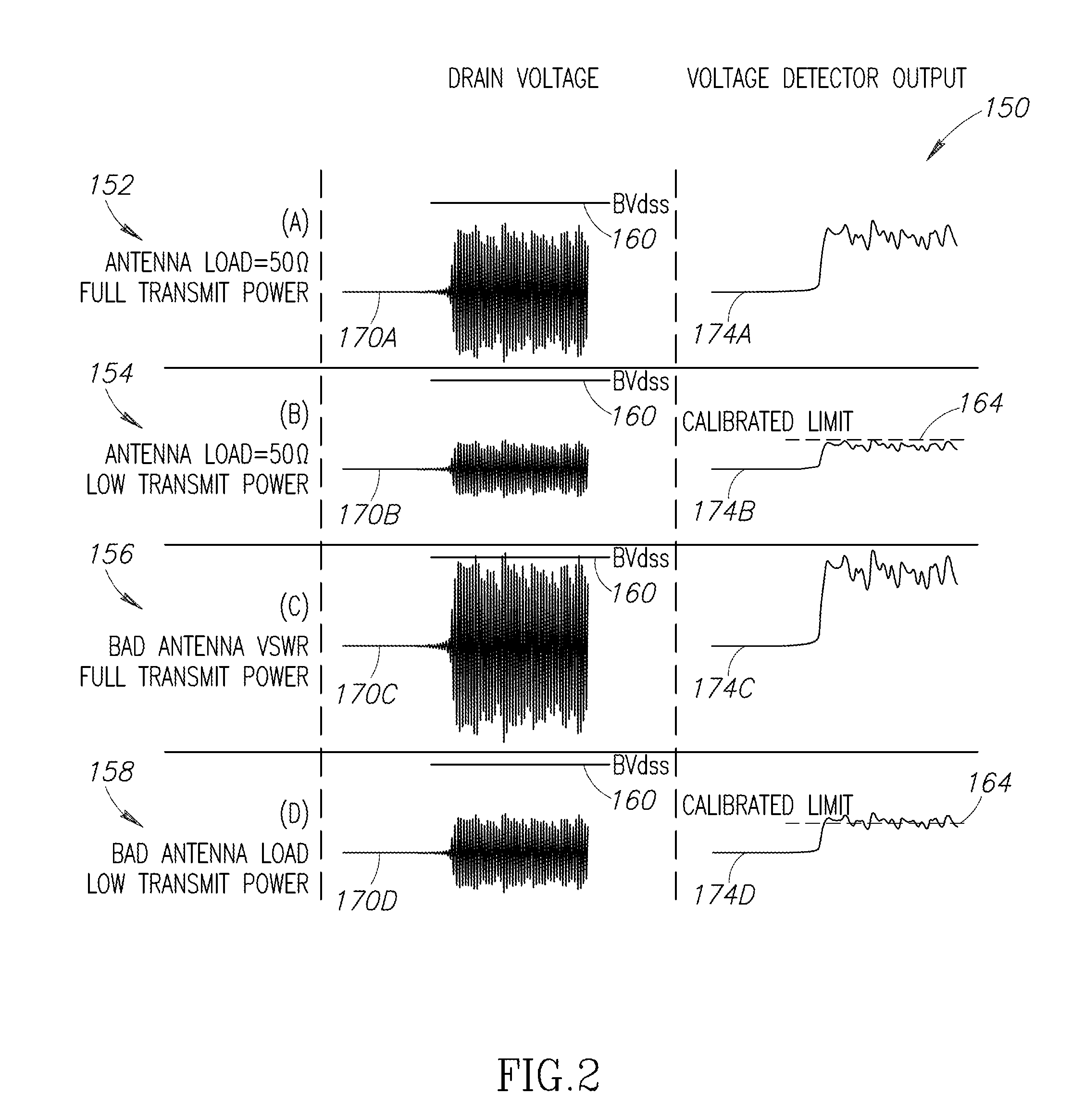
[0017]In a high-power RF transmitter application, a bad load impedance can potentially damage the transmitter power amplifier (PA). The mechanism for this damage may be a reflection of a portion of the transmitted power which produces a voltage at the PA that exceeds the physical limits of the device. The amount of power reflected can be quantified by a quantity referred to as Voltage-Standing-Wave-Ratio (VSWR). In traditional open-loop designs, the reflected voltage will cause a sag in power which automatically compensates for potential excessive voltages and prevents damage. However, closed loop systems (e.g., systems using Cartesian feedback) that attempt to return the power to its design level in response to a sag in voltage, may cause irreversible damage if the system raises the voltage level above the damage threshold of the PA.

[0018]In avionics systems installations, the antenna load can present a high enough VSWR to potentially damage a transmitter with power-leveling feedba...


PUM


Abstract

A radio frequency (RF) power amplifier protection system for a radio. The protection system utilizes a resistive tap connected to the drain of a power amplifier transistor and a high speed voltage detector. The protection system uses short, low-power tests pulses to determine the quality of an antenna load upon tuning the radio to an RF carrier frequency by transmitting the short test pulse. If the measured voltage value exceeds a calibrated value, the power of the RF transmitter is reduced for subsequent operation or the RF transmitter is shut down completely. The invention also includes a system and method for detecting when an antenna is disconnected from a radio using an low frequency AC signal to measure the resistance of an antenna connected to an RF transmitter.

Description

BACKGROUND OF THE INVENTION[0001]1. Field of the Invention[0002]The present invention is directed generally to radio frequency (RF) power amplifiers that are at risk of being damaged as a result of poor load impedances, and more particularly to systems and methods for protecting RF power amplifiers.[0003]2. Description of the Related Art[0004]Power amplifiers are used in RF transmitters to rebroadcast RF signals at high power levels. Because RF transmitters must accurately rebroadcast these signals, the power amplifiers within the transmitters must have high fidelity (e.g., the power amplifiers should maintain linear performance).[0005]In practice, a power amplifier stage may use a variety of silicon die technologies. One example is a field effect transistor (FET) such as a lateral diffused metal-oxide-semiconductor (LDMOS) transistor. The gate of the transistor is typically coupled to an RF input waveform at a given fundamental frequency, which typically comprises an RF carrier mod...

Claims


Application Information

Patent Timeline
IPC IPC(8): G01R19/00
CPCH03F1/523H03G3/3042H03F2200/435H03F3/245
Inventor SHAFER, THOMAS OGLEBRAGG, TONY MONROEALTMAN, GARY
Owner SPECTRALUX
Learn More