Weld schedule for resistance spot welding of aluminum alloy workpieces

Active Publication Date: 2013-02-28
GM GLOBAL TECH OPERATIONS LLC
View PDF14 Cites 21 Cited by
  • Summary
  • Abstract
  • Description
  • Claims
  • Application Information

AI Technical Summary

Benefits of technology

The patent describes a three-stage weld process for aluminum that improves weld quality and reduces power consumption. The process involves heating the electrode / workpiece interface to better connect through oxide coatings and metal surfaces, followed by a cool-down period to prevent overheating. The current flow is then turned off for a short time to allow the weld nugget to cool and solidify. The process is designed to initiate the formation of a good, round, centered molten weld nugget, regardless of the weld electrodes' polarity or the workpiece's fitup. The three-stage weld schedule is more reliable and efficient than conventional methods, and can be used for multiple welds.

Problems solved by technology

Significantly slower rise times will not be able to produce the desired waveforms satisfactorily and welding performance will be compromised.
Again, the objective is to obtain a consistent, stable resistance at the weld site, while not allowing the sheets to melt at the faying interface.

Method used


Image

  • Weld schedule for resistance spot welding of aluminum alloy workpieces
  • Weld schedule for resistance spot welding of aluminum alloy workpieces
  • Weld schedule for resistance spot welding of aluminum alloy workpieces

Examples


Embodiment Construction

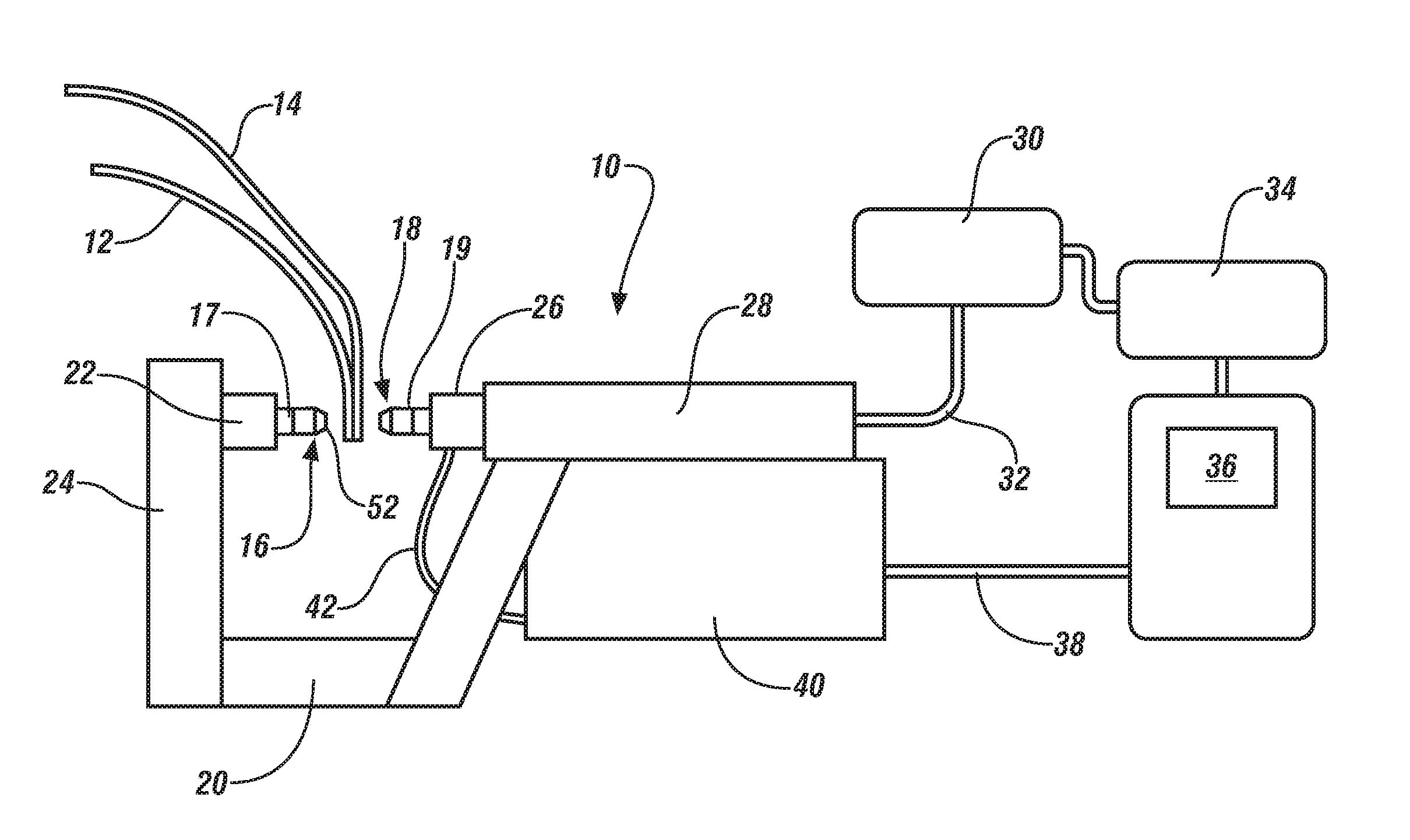
[0024]The weld schedule of this invention may be practiced using welding equipment such as that illustrated schematically in FIG. 1. FIG. 1 in this specification is also presented as FIG. 1 and described substantially as follows in our co-pending U.S. patent application, published as U.S. 2011 / 0266260 and also as FIG. 1 as described in U.S. Pat. No. 6,861,609 of one of us.

[0025]In FIG. 1, a representative spot welding gun apparatus 10 with associated equipment (e.g., items 30, 32, 34, 36, 38, 40, and 42 described below) utilized in spot welding apparatus for aluminum-based alloy(s) workpieces is illustrated. In such welding operations, an assembly of two or more aluminum alloy sheet panels 12 and 14 to be welded is prepared and delivered by a conveyor or other device to the welding gun apparatus 10. The welding gun apparatus is typically mounted on a robot which moves the welding gun apparatus along the edges (e.g., flanges for welding) of aluminum alloy sheet panels 12, 14 to rapid...


PUM

PropertyMeasurementUnit
Timeaaaaaaaaaa
Timeaaaaaaaaaa
Timeaaaaaaaaaa

Abstract

Aluminum-base alloy workpieces have surfaces with films of aluminum oxide which inhibit good contact with weld faces of resistance spot weld electrodes and the faying surfaces of, for example, sheet workpieces stacked for welding. Sometimes, the surfaces of the sheets also are coated with an adhesive or a sealer which further complicates welding. But in accordance with this invention, weld faces of opposing, round, copper welding electrodes are pressed against opposite outside surfaces of the sheets at a spot weld site and weld current is applied to the electrodes in accordance with a three-stage weld schedule to better form each weld. The weld schedule comprises a Conditioning stage (stage 1), a weld nugget Shaping stage (stage 2), and a weld nugget Sizing stage (stage 3).

Description

[0001]This application claims priority based on provisional application 61 / 527,155, titled “Weld Schedule for Resistance Spot Welding of Aluminum alloy Workpieces,” filed Aug. 25, 2011, and which is incorporated herein by reference.TECHNICAL FIELD[0002]This invention pertains to improvement in the formation of resistance spot welds in stack aluminum-base alloy workpieces. More specifically, this invention provides a method utilizing the varied application of current flow values and times in such resistance spot welding in three separate steps or stages to allow weld faces of the electrodes to better engage the aluminum workpieces, to better initiate formation of the molten weld nugget in the center of the faying surface contact zones, and to quickly achieve the target weld nugget size.BACKGROUND OF THE INVENTION[0003]Resistance spot welding typically comprises pressing round weld face surfaces of two opposing, high conductivity, copper electrodes against opposite sides of two or thr...

Claims


Application Information

Patent Timeline
IPC IPC(8): B23K11/11
CPCB23K11/115B23K11/257B23K11/185
Inventor SIGLER, DAVID R.KARAGOULIS, MICHAEL J.
Owner GM GLOBAL TECH OPERATIONS LLC
Why Eureka
Try Eureka