
Aircraft vision system including a runway position indicator

a technology of aircraft vision and indicator, which is applied in the direction of analogue processes, instruments, and specific applications, can solve the problems of discontinuance of landing attempt, poor visibility, and the most difficult task a pilot undertakes, and achieve the effect of improving the accuracy and safety of approach and landing

Active Publication Date: 2013-02-21
HONEYWELL INT INC
View PDF22 Cites 42 Cited by
  • Summary
  • Abstract
  • Description
  • Claims
  • Application Information

AI Technical Summary

Benefits of technology

A runway indicator is a tool that helps pilots land on an airport runway safely and accurately. It provides advanced information to guide the pilot through the approach and landing. This helps to ensure the pilot stays on the correct path and reduces the risk of accident.

Problems solved by technology

The approach to landing and touch down on the runway of an aircraft is probably the most challenging task a pilot undertakes during normal operation.
An approach outside of this envelope can result in an undesirable positioning of the aircraft with respect to the runway, resulting in possibly discontinuance of the landing attempt.
In some instances visibility may be poor during approach and landing operations, resulting in what is known as instrument flight conditions.
Because of poor ground infrastructure, there are limits to how low a pilot may descend on approach prior to making visual contact with the runway environment for runways having an instrument approach procedure.
These requirements limit low visibility approaches to a small number of runways.
However, two concerns related to a synthetic vision system are 1) the lacking of or insufficient separated integrity verification for the displayed information, and 2) the lack of sufficient integrity or short-term critical availability during the final approach phase of data sources used to generate the visual display elements for navigation and verification purposes.

Method used


Image

  • Aircraft vision system including a runway position indicator
  • Aircraft vision system including a runway position indicator
  • Aircraft vision system including a runway position indicator

Examples


Embodiment Construction

[0018]The following detailed description is merely illustrative in nature and is not intended to limit the embodiments of the subject matter or the application and uses of such embodiments. Any implementation described herein as exemplary is not necessarily to be construed as preferred or advantageous over other implementations. Furthermore, there is no intention to be bound by any expressed or implied theory presented in the preceding technical field, background, brief summary, or the following detailed description.

[0019]A system and method, that will allow pilots to descend to a low altitude, e.g., to 100 feet or below, includes comparing standard guidance instruments / symbology and separately generated visual display elements. The separately generated visual display elements are indicative of current aircraft state such as its true position and altitude, and are produced with the data sources substantially independent of or substantially modified from the data used in generating s...


PUM


Abstract

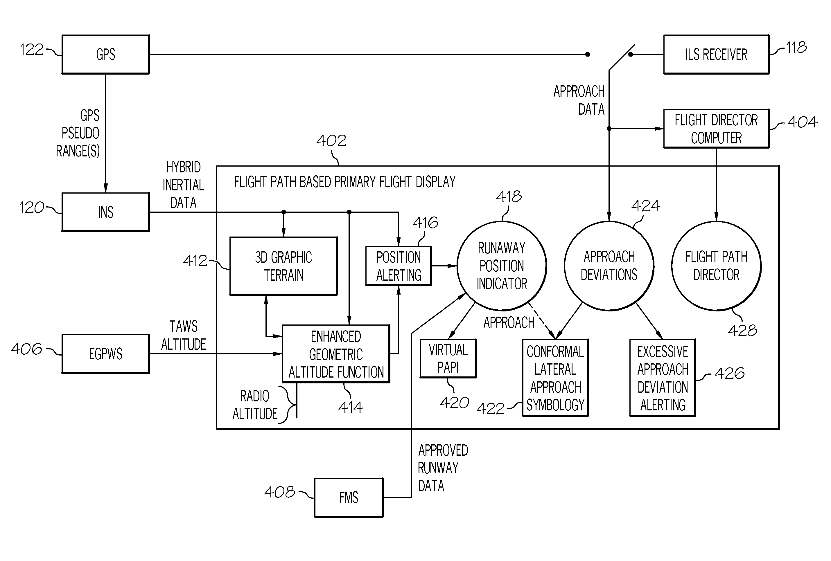
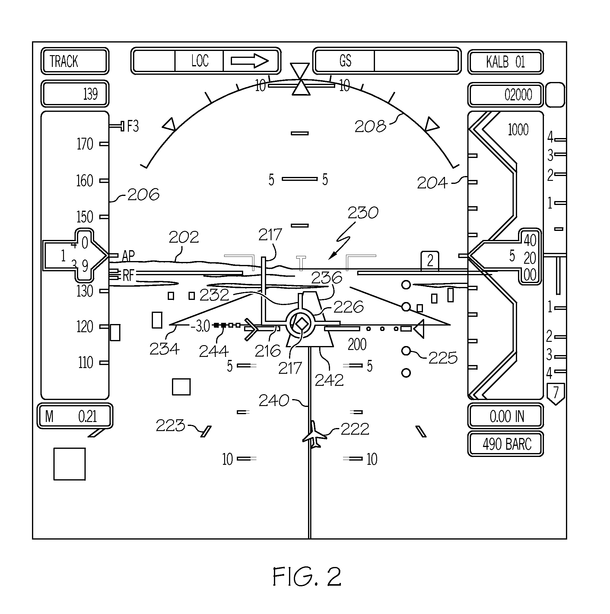
A runway indicator is displayed overlying a target runway for providing supplementary guidance to support the pilot's ability to fly a stabilized approach. The highlighted runway position indicator provides cues to verify that the aircraft is continuously in a position to complete a normal landing using normal maneuvering during the instrument segment of an approach and includes a landing threshold, a landing zone on the runway, an approach line leading to the runway, an outline highlighting the sides and ends of the runway, a rectangle larger than and surrounding the runway, and a visual precision path approach indicator.

Description

TECHNICAL FIELD[0001]The present invention generally relates to a system for improving a pilot's ability to complete an approach to a runway and more particularly to a system for displaying information to support a pilot's ability to fly a stabilized approach.BACKGROUND[0002]The approach to landing and touch down on the runway of an aircraft is probably the most challenging task a pilot undertakes during normal operation. To perform the landing properly, the aircraft approaches the runway within an envelope of attitude, course, speed, and rate of descent limits. The course limits include, for example, both lateral limits and glide slope limits. An approach outside of this envelope can result in an undesirable positioning of the aircraft with respect to the runway, resulting in possibly discontinuance of the landing attempt.[0003]In some instances visibility may be poor during approach and landing operations, resulting in what is known as instrument flight conditions. During instrume...

Claims


Application Information

Patent Timeline
IPC IPC(8): G01C21/00G01C23/00
CPCG08G5/025G08G5/0021
Inventor FEYEREISEN, THEA L.WYATT, IVAN SANDYHE, GANGCONNOR, GLENN
Owner HONEYWELL INT INC
Learn More