
Discharge circuit for capacitor

a capacitor and discharge circuit technology, applied in the direction of dc-ac conversion without reversal, propulsion by batteries/cells, electric devices, etc., can solve the problems of increasing the size of the system and the cost of manufacturing the system, and achieve the effect of suppressing the heat generated by the resistor

Inactive Publication Date: 2013-02-14
DENSO CORP
View PDF0 Cites 9 Cited by
  • Summary
  • Abstract
  • Description
  • Claims
  • Application Information

AI Technical Summary

Benefits of technology

The present disclosure provides a circuit that reduces the number of components by using a series-connected resistor and a switch to form a closed loop circuit for discharging a capacitor. This circuit eliminates the need for additional components and reduces the size and cost of the power conversion system. The circuit also includes voltage detecting circuits and control units for each circuit component, allowing for individual discharging of capacitors connected to the boost converter and DC to AC converting circuit. This ensures quick discharging of the capacitors and reduces power consumption during normal operation. Additionally, the circuit prevents power consumption and heat generation by configuring a closed loop circuit only when necessary.

Problems solved by technology

In this instance, size of the system may increase and the cost of the manufacturing the system may increase as well.

Method used


Image

  • Discharge circuit for capacitor
  • Discharge circuit for capacitor
  • Discharge circuit for capacitor

Examples


first embodiment

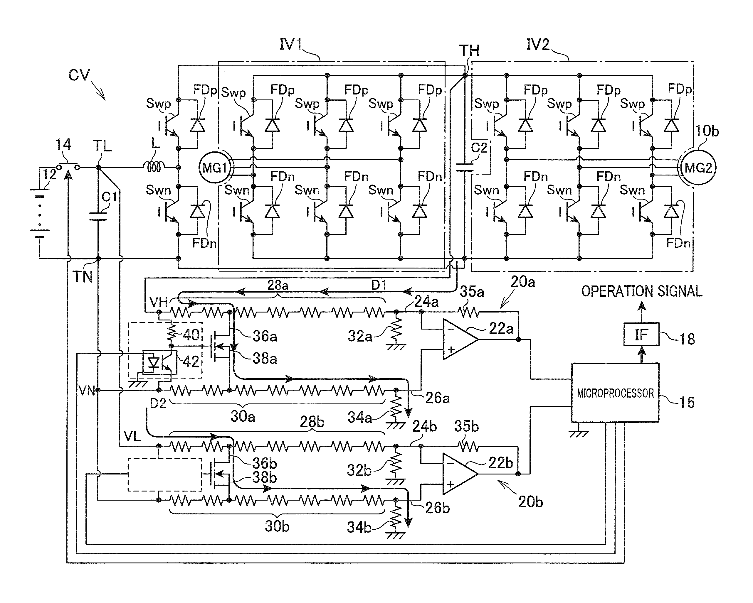
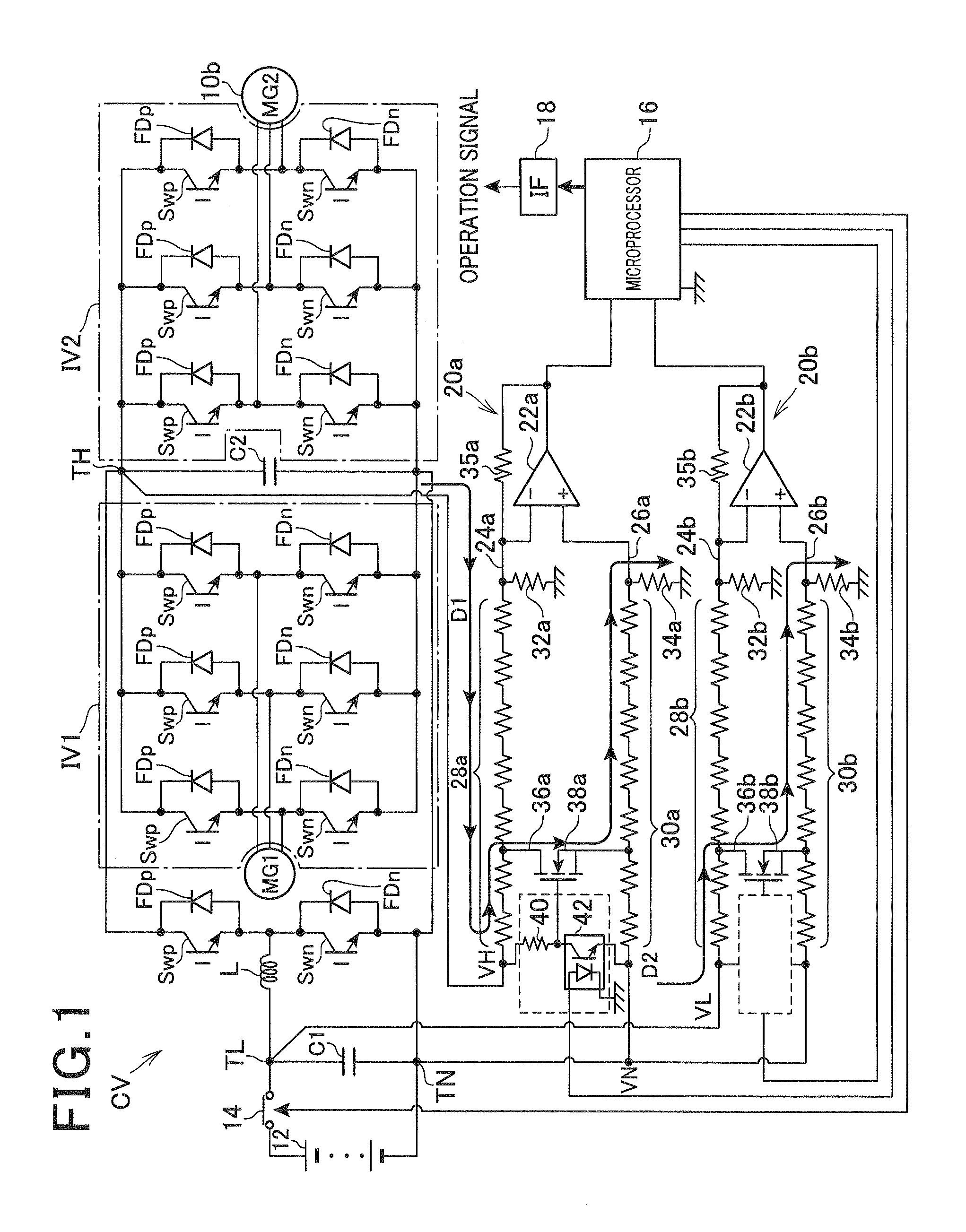
[0023]With reference to the drawings, hereinafter will be described a discharge circuit of a capacitor adapted to a power conversion system disposed in a parallel series hybrid vehicle according to the first embodiment.

[0024]FIG. 1 is a system configuration according to the first embodiment.

[0025]A first motor generator 10a and a second motor generator 10b as shown in FIG. 1 are mechanically connected to the driving wheel and the internal combustion engine via a power splitter (not shown). The first motor generator 10a is electrically connected to an inverter IV1 and the second motor generator 10b is electrically connected to an inverter IV2. These inverters IV1 and IV2 are configured to receive the output voltage of a boost converter CV which boosts the voltage of the high voltage battery 12.

[0026]The high voltage battery 12 is a secondary battery having the terminal voltage 100 volts or more, ex, 280 volts. A lithium-ion battery, nickel-metal hydride battery can be used for the hi...

second embodiment

[0075]With reference to the drawings, hereinafter is described the second embodiment wherein the differences between the above-described first embodiment and the second embodiment is mainly described.

[0076]FIG. 5 is a block diagram showing a system configuration according to the second embodiment. Regarding components in FIG. 5 which is the same as the components as shown in FIG. 1, the same reference numbers are applied.

[0077]As shown in FIG. 5, the microprocessor 16 outputs operation signals via an interface device 18 in order to operate the switching elements of the boost converter CV and the inverters IV1 and IV2. The microprocessor 16 outputs the operation signals to the drive unit Dup corresponding to the high side switching elements of the respective units (boost converter CV and the inverters IV1 and IV2) and the drive unit Dun corresponding to the low side switching elements of the respective units.

[0078]The drive units Dup and Dun are disposed in the high voltage system an...


PUM


Abstract

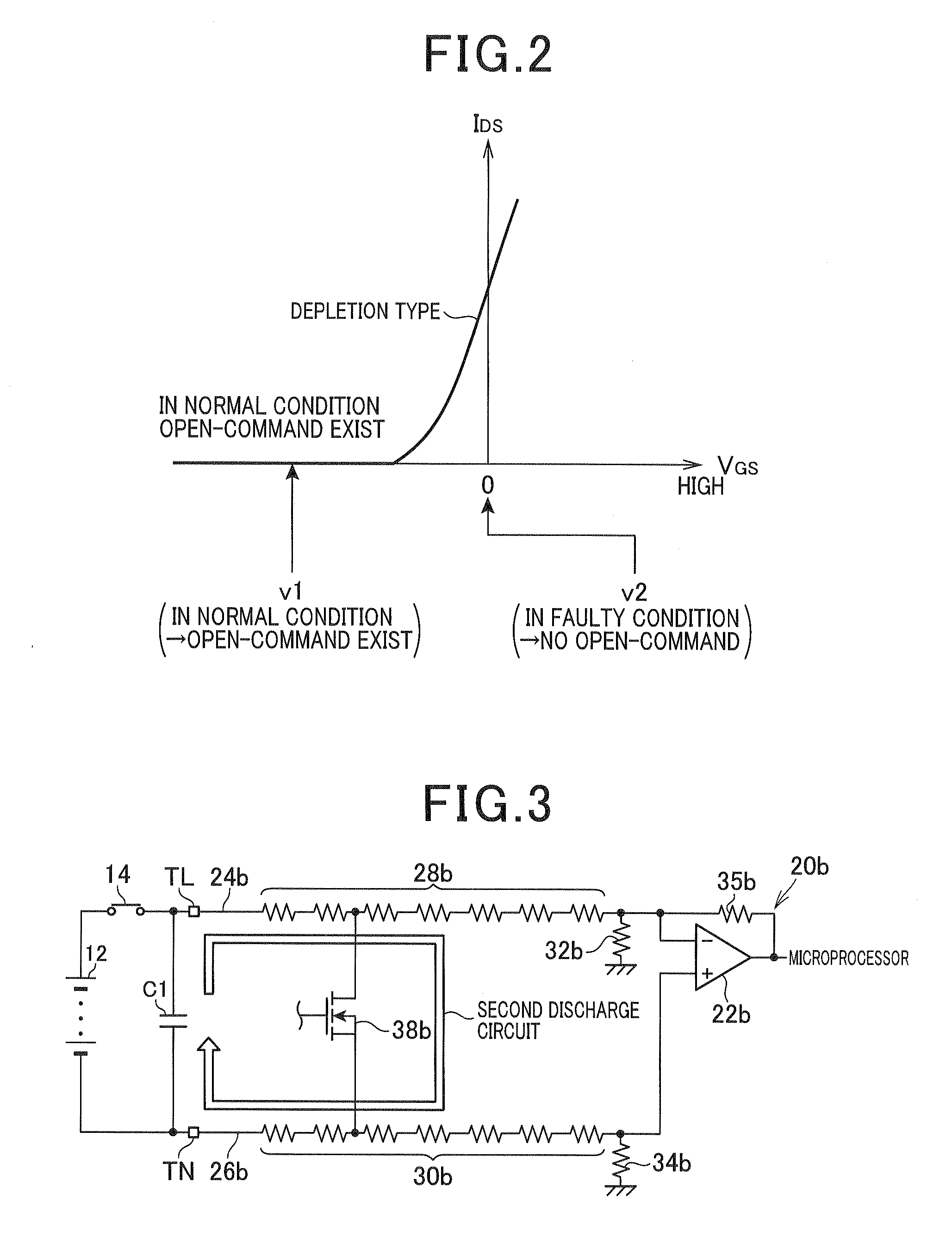
A discharge circuit for discharging a capacitor disposed in a power conversion circuit. The discharge circuit includes: a conduction path connecting the power conversion circuit and input terminals; plural resistors disposed in the conduction path, dividing voltage difference between voltage at the input terminal and reference voltage; a connection path connecting a pair of conduction paths; a switch disposed in the connection path, which opens and closes the connection path, the switch being controlled electrically; and a control unit that controls the switch to be opened or closed, the control unit controls the switch to be closed in order to make a closed loop circuit including the capacitor and the connection path. The connection path is disposed between the pair of conduction paths to include at least one resistor of the plurality of resistors in the closed loop circuit when the switch is closed by the control unit.

Description

CROSS-REFERENCE TO RELATED APPLICATION[0001]This application is based on and claims the benefit of priorities from earlier Japanese Patent Application No. 2011-172551 filed on Aug. 8, 2011, the description of which are incorporated herein by reference.BACKGROUND[0002]1. Technical Field[0003]The present disclosure relates to discharge circuits and, more particularly to a discharge circuit for capacitors adapted to a system having a DC power source, a power conversion circuit and a voltage detecting circuit.[0004]2. Description of the Related Art[0005]Conventionally, the discharge circuit for capacitors has been widely used for a power conversion system. In the power conversion system, the DC power source is connected to the power conversion circuit via a pair of input terminals to which the capacitor is connected, and the voltage detecting circuit is connected to the pair of input terminals so as to detect voltage therebetween. For example, Japanese Patent Application Laid-Open Publi...

Claims


Application Information

Patent Timeline
Patent Type & Authority Applications(United States)
IPC IPC(8): H02M7/537
CPCB60L3/003B60L11/123B60L11/14B60L15/007B60L2210/14B60L2210/40Y02T10/6217H02M2001/322Y02T10/7077Y02T10/7241Y02T10/7022Y02T10/7225H02M7/48B60L50/61B60L50/16Y02T10/62Y02T10/64Y02T10/70Y02T10/72Y02T10/7072H02M1/322
Inventor FUKUTA, JUNICHI
Owner DENSO CORP
Learn More