Capacitive touch panel and a method of manufacturing the same
a capacitive touch and touch technology, applied in the field of capacitive touch panels, can solve the problems of product defective appearance, reduced production yield, difficult to realize, etc., and achieve the effects of reducing the visibility reducing the light reflection of the metal jumper, and being easy to perceiv
- Summary
- Abstract
- Description
- Claims
- Application Information
AI Technical Summary
Benefits of technology
Problems solved by technology
Method used
Image
Examples
first embodiment
The First Embodiment
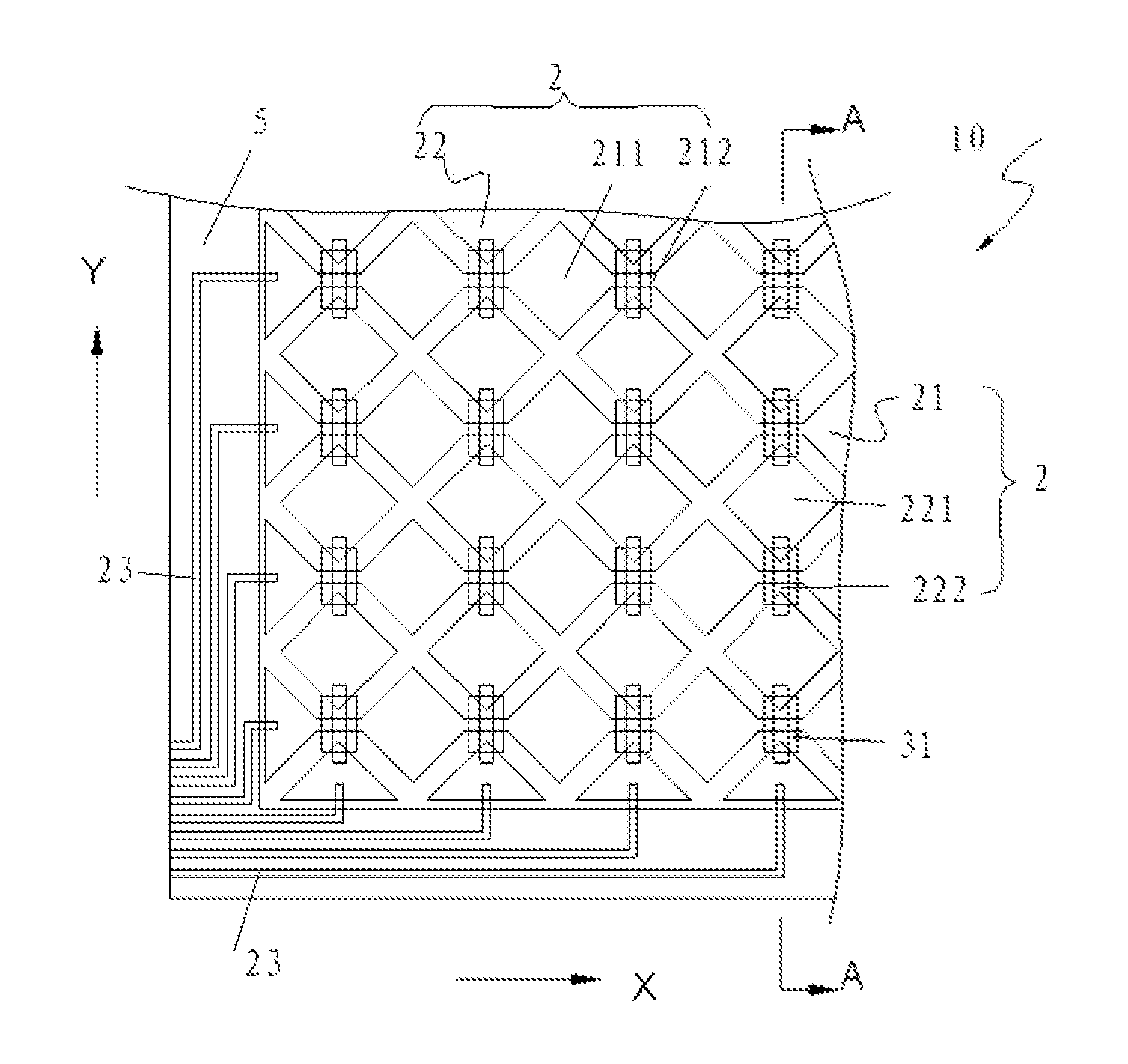
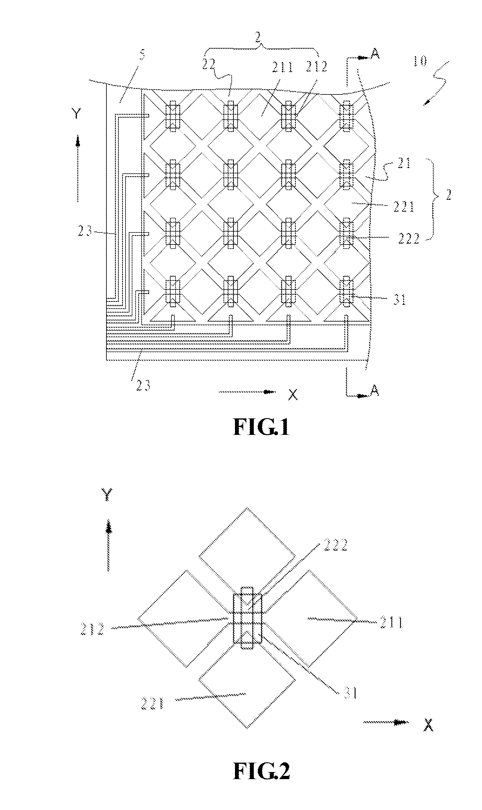
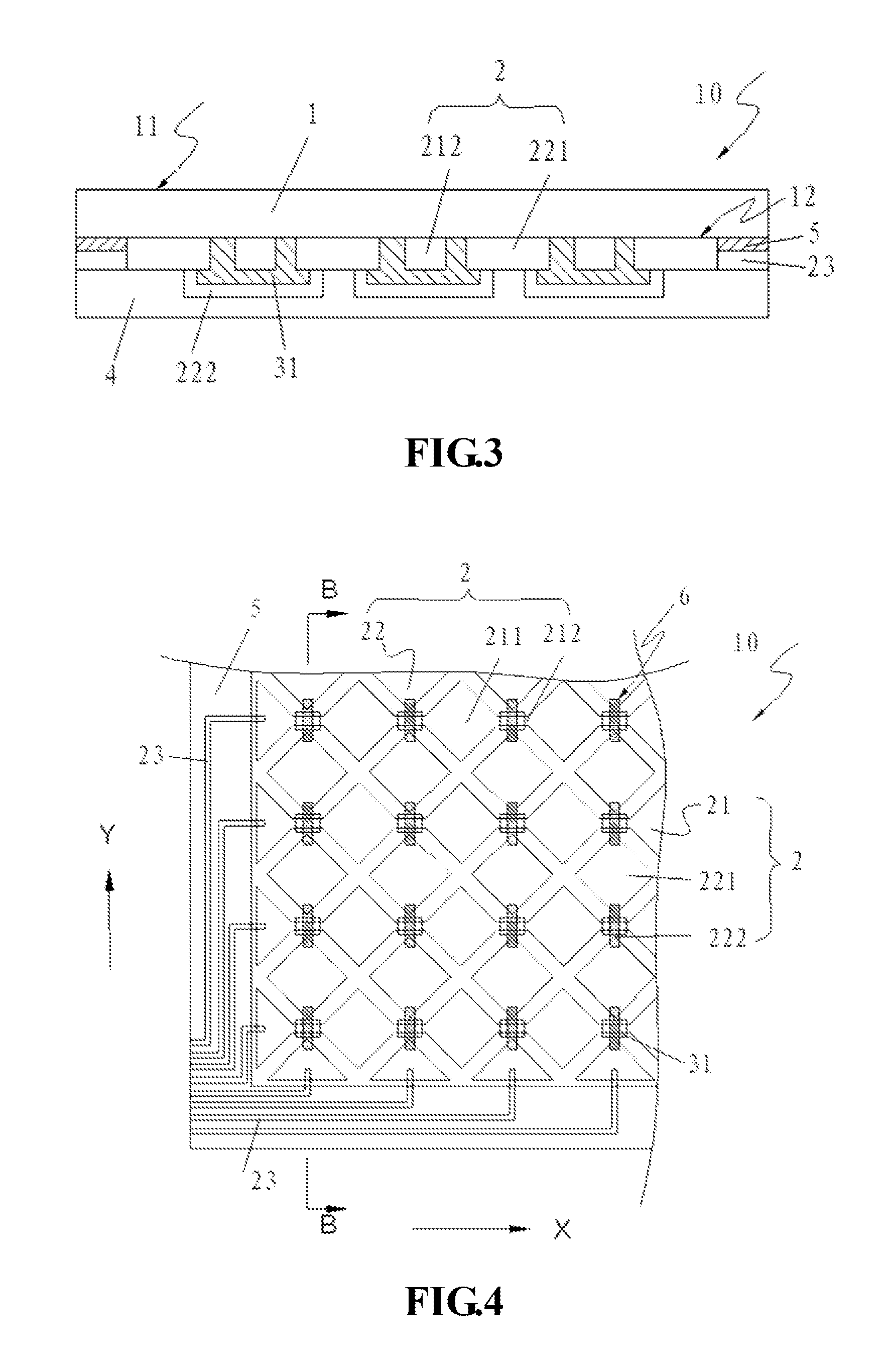
[0026]Referring to FIG. 4, FIG. 5 and FIG. 6A, a capacitive touch panel 10 comprises a transparent substrate 1, a sensing circuit layer 2, a protective layer 4, a black matrix 5 and a mask layer 6. The sensing circuit layer 2 is set between the transparent substrate 1 and the protective layer 4, and is placed on the lower surface 12 of the transparent substrate 1 while the upper surface 11 is used for touching. The sensing circuit layer 2 comprises a plurality of first-axis electrodes 21 and second-axis electrodes 22, located on X-axis and Y-axis of the vertical coordinate axes respectively. Each first-axis electrode 21 has a plurality of first electrodes 211 and first-axis wires 212 connected to two adjacent first electrodes 211; each second-axis electrode 22 has a plurality of second electrodes 221 and second-axis wires 222 connected to two adjacent second electrodes 221. Metal jumpers are usually used for the second-axis wires 222; the first-axis wires 212 and...
second embodiment
The Second Embodiment
[0033]Referring to FIG. 7A and FIG. 7B, for a capacitive touch panel 10, the structure is similar to the first embodiment and comprises of a transparent substrate 1, a sensing circuit layer 2, a protective layer 4, a black matrix 5, and a mask layer 6. First electrodes 211, first-axis wires 212. and second electrodes 221 of the sensing circuit layer 2 are placed on a second surface 12 of the transparent substrate 1. Second-axis wires 222 are metal jumpers; the first-axis wires 212 and the metal jumpers are insulated by insulating sheets 31. The insulating sheets 31 are made of black or melanocratic insulating materials, act as a mask layer, and are placed above the metal jumpers. Width (along Y-axis) of the insulating sheets 31 is more than width (along Y-axis) of the first-axis wires 212 but less than length (along Y-axis) of the second-axis wires 222. Length (along X-axis) of the insulating sheets 31 is not less than the width (along X-axis) of the second-axis...
third embodiment
The Third Embodiment
[0035]Referring to FIG. 8, for a capacitive touch panel 10, the structure is similar to the first embodiment, wherein the difference lies in insulation setting. The capacitive touch panel 10 comprises a transparent substrate 1, a sensing circuit layer 2, a protective layer 4, a black matrix 5, a mask layer 6, and an insulating layer 3, which has a plurality of through-holes 32. First-axis electrodes 21 and second-axis electrodes 22 are located on first surface 33 of the insulating layer 3. Each first-axis electrode 21 has a plurality of first electrodes 211 and first-axis wires 212, which connect two adjacent first electrodes 211. Each second-axis electrode 22 has a plurality of second electrodes 221 placed between two corresponding adjacent first-axis electrodes 21, interlacing with the first electrodes 211 at intervals; each second-axis electrode 22 also has a plurality of second-axis wires 222 which are metal jumpers set on the second surface 34 of the insulat...
PUM
| Property | Measurement | Unit |
|---|---|---|
| Electrical conductor | aaaaa | aaaaa |
| Transparency | aaaaa | aaaaa |
| Reflectance | aaaaa | aaaaa |
Abstract
Description
Claims
Application Information
 - R&D
- Intellectual Property
- Life Sciences
- Materials
- Tech Scout
- Unparalleled Data Quality
- Higher Quality Content
- 60% Fewer Hallucinations
Browse by: Latest US Patents, China's latest patents, Technical Efficacy Thesaurus, Application Domain, Technology Topic, Popular Technical Reports.
© 2025 PatSnap. All rights reserved.Legal|Privacy policy|Modern Slavery Act Transparency Statement|Sitemap|About US| Contact US: help@patsnap.com


