
Thermoelectric power module

a technology of thermoelectric power module and thermal insulation layer, which is applied in the direction of thermoelectric device details, basic electric elements, electric devices, etc., can solve the problems of nickel diffusion into a solder layer, segregation, and inability to precisely prevent the diffusion of thin diffusion prevention layer having a thickness of several micrometers, etc., to achieve the effect of suppressing the diffusion of nickel

Active Publication Date: 2013-02-07
KOMATSU LTD
View PDF2 Cites 28 Cited by
  • Summary
  • Abstract
  • Description
  • Claims
  • Application Information

AI Technical Summary

Benefits of technology

The present invention proposes a solution to prevent nickel from diffusing into solder in a high temperature environment. This is achieved by changing nickel to an intermetallic compound of nickel-tin. The technical effect of this innovation is to provide a thermoelectric power module that can withstand long-term use in high temperature environments where the temperature reaches 250°C or higher.

Problems solved by technology

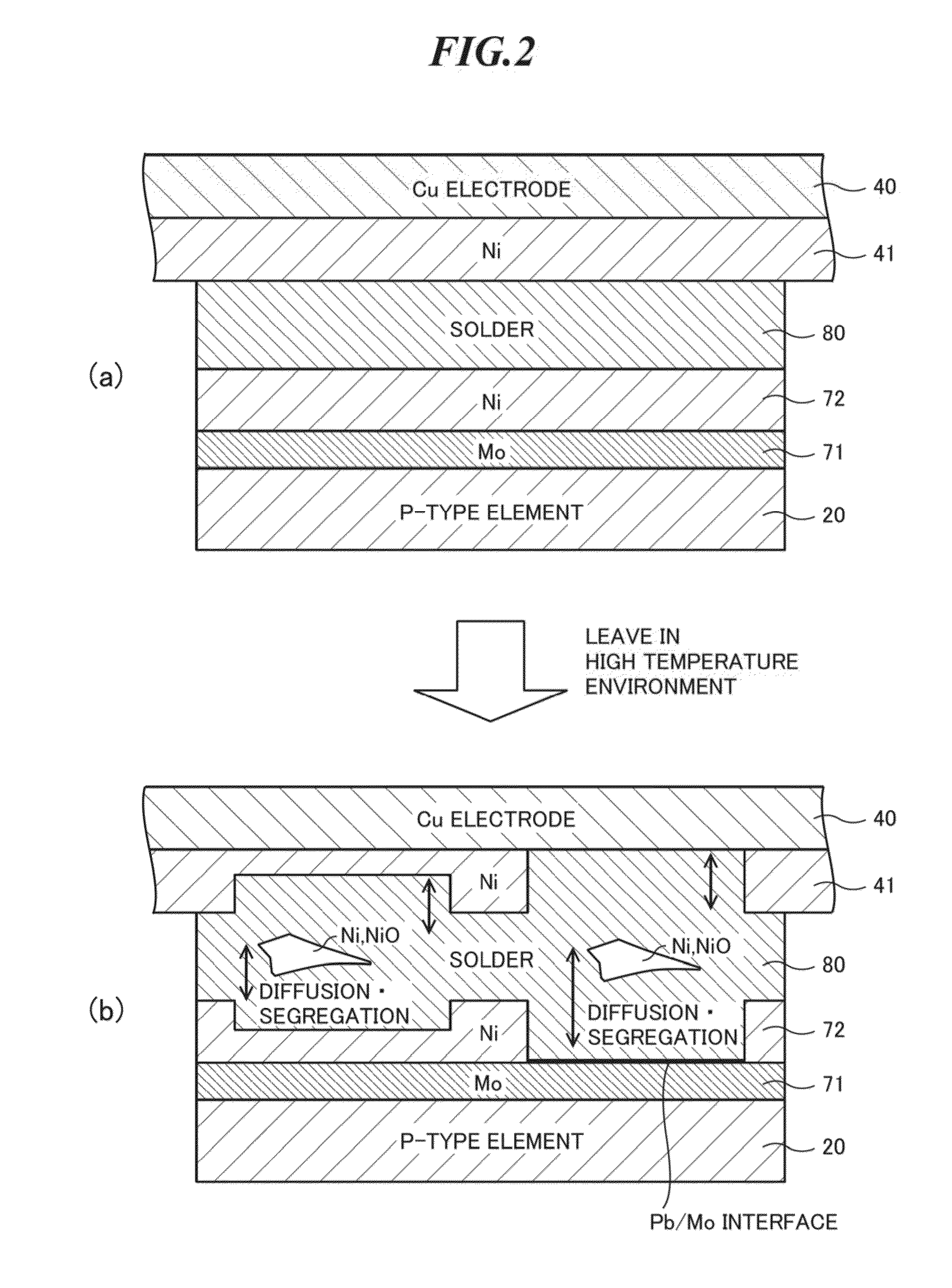
In JP-A-10-135523, it is pointed out that in a thermoelectric device using nickel as a diffusion prevention layer for preventing solder from diffusing into a thermoelectric element, a thin diffusion prevention layer having a thickness of several micro meters cannot precisely prevent the diffusion.
However, in the high temperature environment where a temperature of a higher temperature portion exceeds 250° C., and in the case where nickel is used as a diffusion prevention layer for preventing solder from diffusing into thermoelectric element, on the contrary, there occurs a problem that nickel diffuses into a solder layer and makes segregation, and a resistance value of a joined interface increases.

Method used


Image

  • Thermoelectric power module
  • Thermoelectric power module
  • Thermoelectric power module

Examples


first embodiment

[0040]FIG. 3 is an enlarged cross section diagram showing a part of a thermoelectric power module according to the present invention. FIG. 3 shows P-type element 20 as an example of a thermoelectric power element. As shown in FIG. 3, in this thermoelectric power module, a diffusion prevention layer 71 is formed of molybdenum (Mo) on a main surface (upper surface in the drawing) of a thermoelectric power element (P-type element) 20, and a diffusion prevention layer 73 is formed of an intermetallic compound of nickel-tin (Ni—Sn) on a surface of the diffusion prevention layer 71 opposite to the thermoelectric power element side.

[0041]On the other hand, a diffusion prevention layer 42 is formed of an intermetallic compound of nickel-tin (Ni—Sn) on a main surface (lower surface in the drawing) of an electrode 40 formed of copper (Cu). Further, the diffusion prevention layer 73 and the diffusion prevention layer 42 are joined to face each other by a solder layer 80 containing lead (Pb) at...

second embodiment

[0049]FIG. 5 is an enlarged cross section diagram showing a part of a thermoelectric power module according to the present invention. FIG. 5 shows a P-type element 20 as an example of a thermoelectric power element. As shown in FIG. 5, in this thermoelectric power module, a diffusion prevention layer 71 is formed of molybdenum (Mo) on a main surface (upper surface in the drawing) of the thermoelectric power element (P-type element) 20, and a diffusion prevention layer 72 is formed of nickel (Ni) on a surface of the diffusion prevention layer 71 opposite to the thermoelectric power element side. Further, a diffusion prevention layer 73 is formed of an intermetallic compound of nickel-tin (Ni—Sn) on a surface of the diffusion prevention layer 72 opposite to the diffusion prevention layer 71 side.

[0050]On the other hand, a diffusion prevention layer 41 is formed of nickel (Ni) on a main surface (lower surface in the drawing) of an electrode 40 formed of copper (Cu), and a diffusion pre...


PUM


Abstract

A thermoelectric power module capable of withstanding a long time use in a high temperature environment where a temperature (Th) of a higher temperature portion exceeds 250° C. The thermoelectric power module includes: a thermoelectric power element; a first diffusion prevention layer consisting of molybdenum (Mo) and disposed on a surface of the thermoelectric power element; a second diffusion prevention layer consisting of an intermetallic compound of nickel-tin (Ni—Sn) and disposed on a surface of the first diffusion prevention layer opposite to the thermoelectric power element side; an electrode; a third diffusion prevention layer consisting of an intermetallic compound of nickel-tin (Ni—Sn) and disposed on a surface of the electrode; a solder layer containing lead (Pb) at not less than 85% and configured to join the second diffusion prevention layer and the third diffusion prevention layer to each other.

Description

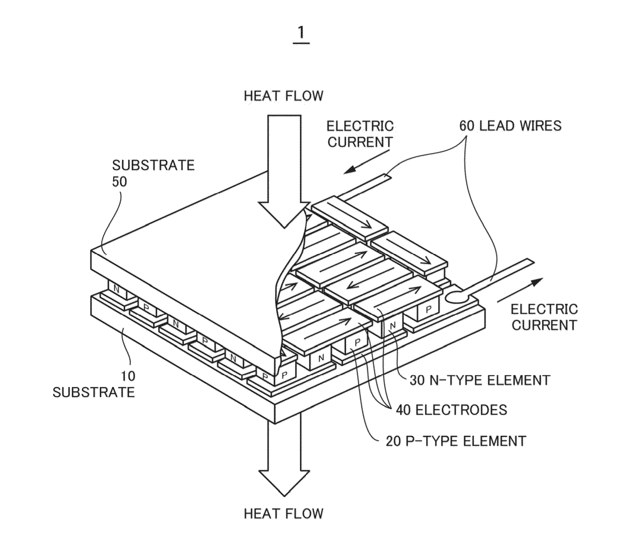
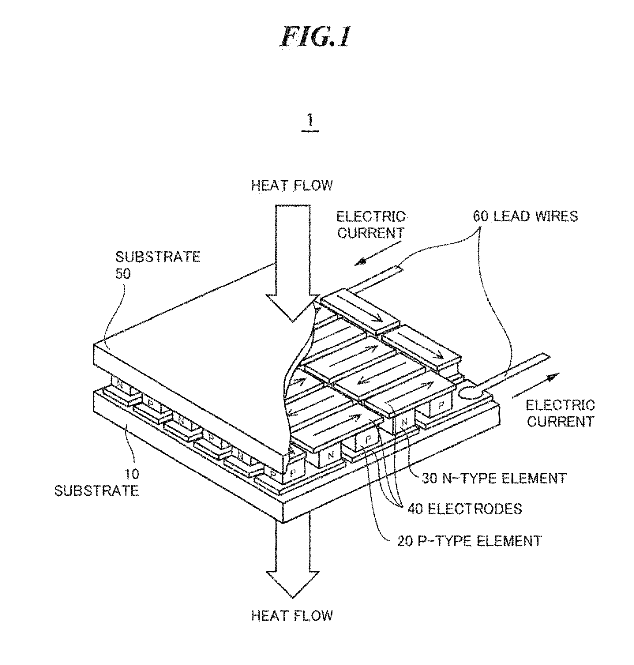
TECHNICAL FIELD[0001]The present invention relates to a thermoelectric power module using thermoelectric elements and thereby generating electricity by utilizing difference in temperature.BACKGROUND ART[0002]Conventionally, thermoelectric generation of electricity is known in which the thermoelectric power elements are disposed between a heat exchanger at a higher temperature side and another heat exchanger at a lower temperature side generate electricity. The thermoelectric power element is an application s a thermoelectric effect to be called Seebeck effect. In the case where a semiconductor material is used as a thermoelectric material, the thermoelectric power module is configured by combining at least one thermoelectric power element formed of a P-type thermoelectric material and at least one thermoelectric power element formed of an N-type thermoelectric material. Such a thermoelectric power module has a simple structure and can be easily treated, and a stable characteristic c...

Claims


Application Information

Patent Timeline
IPC IPC(8): H01L35/02
CPCH01L35/08H10N10/817H10N10/00H10N10/10H10N10/17
Inventor KAJIHARA, TAKESHIISHIDA, KOUICHIFUJIMOTO, SHINICHIMIZUKAMI, HIROYUKI
Owner KOMATSU LTD
Learn More