
Pseudo surface microwave produced plasma shielding system

a technology of surface microwave and shielding system, which is applied in the direction of plasma technique, coating, electric discharge lamps, etc., can solve the problems of not allowing sound to be reflected, part of the propagation mechanism due to thermal motion of ions cannot be completely cancelled, and so as to reduce the development of eddy current, reduce the amount of drag and eddy current reduction, and improve the flight performance and flight economy of aircra

Active Publication Date: 2007-08-14
HIGMAN KUMIKO I
View PDF8 Cites 38 Cited by
  • Summary
  • Abstract
  • Description
  • Claims
  • Application Information

AI Technical Summary

Benefits of technology

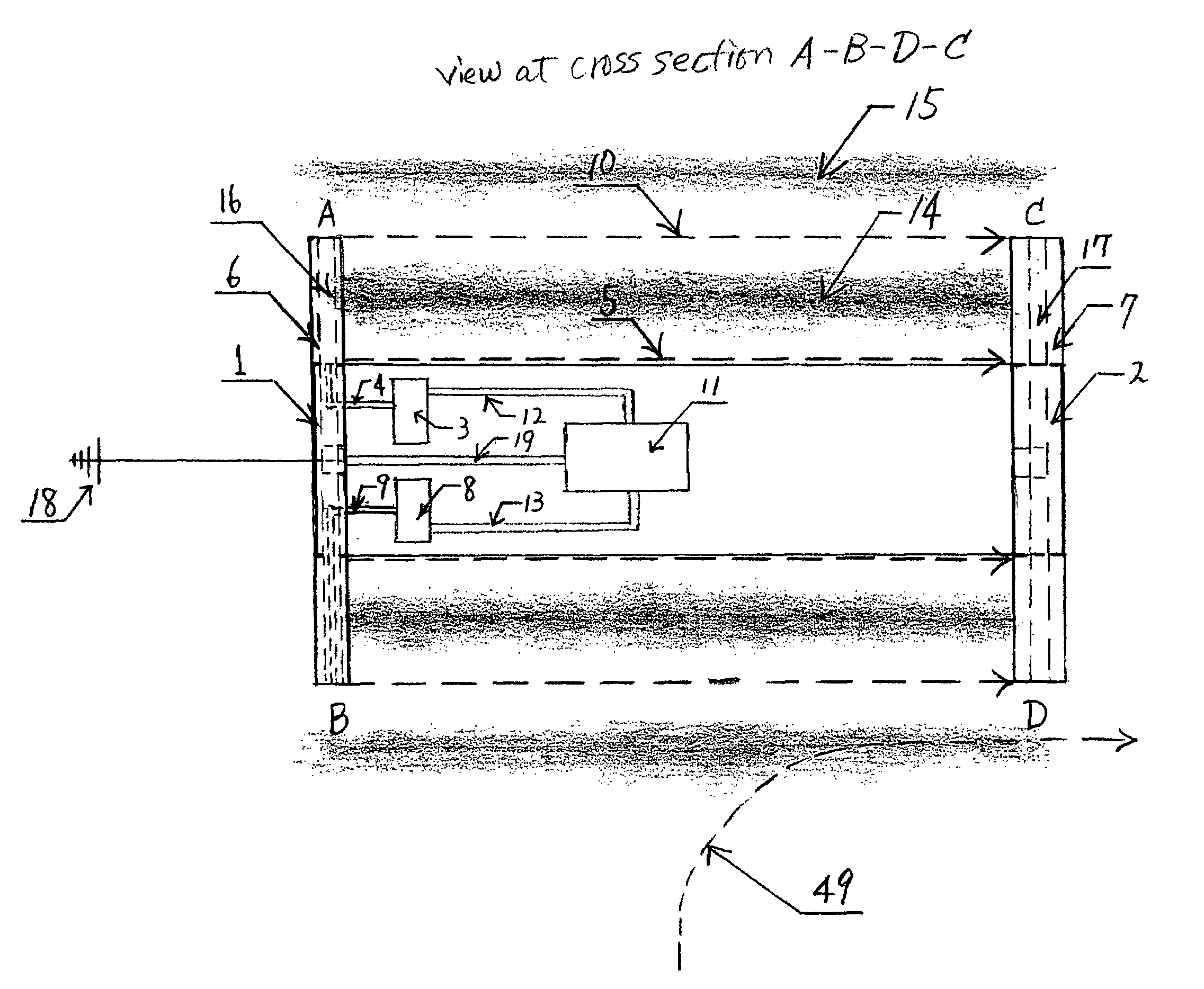
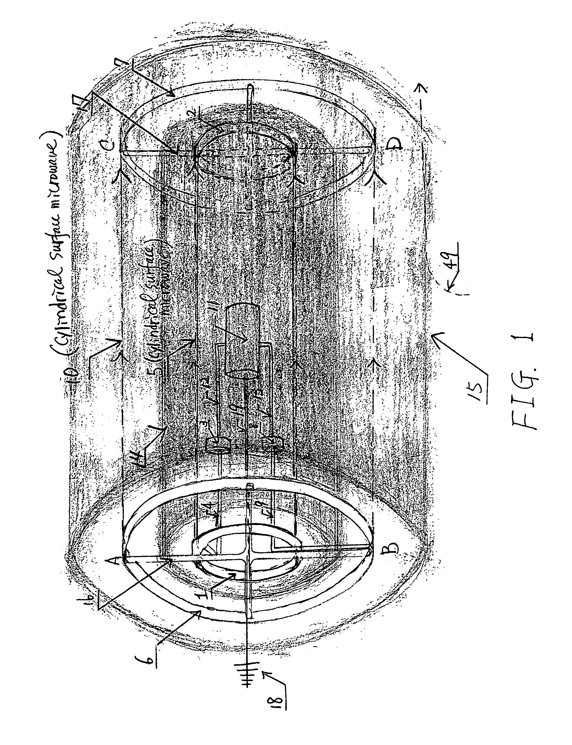
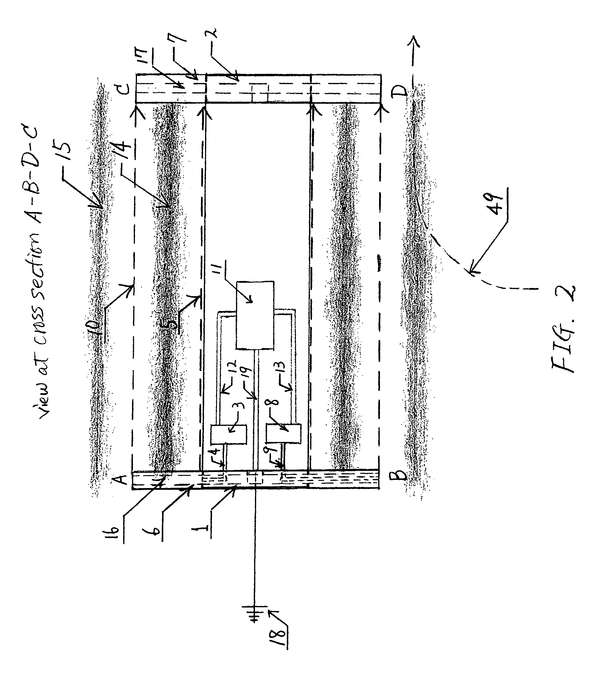
[0012]The present invention extends its defense system application to a stealth capability from SONAR detection. The same microwave launcher-receptor system configuration with a simple modification to employ a microwave antenna can counter an incoming sound wave launched from SONAR. When a sound wave enters the plasma region, it changes the mechanism of propagation from the propagation of an ordinary sound wave to propagation of an ion acoustic wave. The ion acoustic wave propagates partially by thermal motions of ions and partially by electric field oscillation. The part of the propagation mechanism due to electric field oscillation can be canceled by an electric field of 180° out of phase with the wave propagation field. The mobile microwave antenna equipped in this plasma shielding system generates this counteracting electric field to cancel the propagation field. The part of the propagation mechanism due to thermal motions of ions cannot be completely canceled since the ion temperature cannot practically be controlled to be zero. However, the ion temperature perpendicular to the magnetic field in the plasma region can be controlled to be nearly zero by suppressing the diffusion of ions across the magnetic field by increasing the intensity of the magnetic field. The intensity of the magnetic field can be controlled by using A.I. equipped on board and by adjusting intensity of the surface microwaves. When this happens, the ion acoustic wave becomes an Alfven wave propagating along the magnetic field in the plasma region. Therefore, this plasma shielding system can trap and confine a sound wave in the plasma region and does not allow the sound to be reflected. A magnetosonic wave generated by a nuclear explosion can also be altered to Alfven wave in this plasma shield environment since the magnetic field in this plasma shield suppresses ion and electron diffusion, i.e., their collisions.
[0014]The present invention can also extend its application to a flow field control system such as a boundary layer and turbulence control system, and lift control system to improve flight performance and flight economy of aircraft. When pseudo surface microwaves propagate along entire aircraft surfaces in the streamwise direction, these surface microwaves push plasma particles in the streamwise direction and away from the surfaces at the same time. Through collisions of these plasma particles with neutral air particles near the surfaces, the motions of these plasma particles result in countering the momentum transfer of air particles to the aircraft surfaces as a drag force and also result in reducing the development of eddy currents near surfaces, which ultimately causes turbulence. The amount of drag reduction and eddy current reduction can be controlled by using A.I. equipped on board and by adjusting the intensity of surface microwaves. The pseudo surface microwave can also be used to improve lift performance. The pressure on the lower surface of an airfoil can be increased when a plane surface microwave is launched from the tail end of the airfoil preferably with the distance of boundary layer thickness, and propagates through the plasma region slightly away from the surface preferably with the distance of boundary layer thickness in the opposite direction to the streamwise direction. This is because this surface wave pushes plasma particles against the streamwise direction and toward the surface due to the radiation pressure and due to the effect of the ponderomotive force from the surface microwave and these motions of plasma particles change the momenta of incoming high speed air particles to the momenta that transfer as a surface pressure. An increase of lower surface pressure of the airfoil results in increasing lift of the airfoil. The amount of lift increase can be controlled by using A.I. equipped on board by adjusting the intensity of the surface microwave. In this manner, a pseudo surface microwave produced plasma shielding system can control a flow field around an aircraft and contribute to improved flight performance and flight economy.

Problems solved by technology

The part of the propagation mechanism due to thermal motions of ions cannot be completely canceled since the ion temperature cannot practically be controlled to be zero.
Therefore, this plasma shielding system can trap and confine a sound wave in the plasma region and does not allow the sound to be reflected.
Through collisions of these plasma particles with neutral air particles near the surfaces, the motions of these plasma particles result in countering the momentum transfer of air particles to the aircraft surfaces as a drag force and also result in reducing the development of eddy currents near surfaces, which ultimately causes turbulence.
An increase of lower surface pressure of the airfoil results in increasing lift of the airfoil.

Method used


Image

  • Pseudo surface microwave produced plasma shielding system
  • Pseudo surface microwave produced plasma shielding system
  • Pseudo surface microwave produced plasma shielding system

Examples


Embodiment Construction

[0028]The objectives of the present invention are to provide the ways to produce the plasma shielding system, to provide the ways to apply this plasma shielding system to the engineering field, and to provide the theoretical explanations to the mechanisms of these applications. Therefore, this invention is not limited to the particular processes, geometric configurations, materials, physical properties, e.g., the type of surface waves not limiting to microwaves, and components and their positions in the system disclosed herein as such processes, geometric configurations, materials, physical properties, and components and their positions in the system may vary. The terminology herein is used to describe the particular embodiments only. Therefore, the scope of this invention will not be limited by the terminology herein but will be limited by the following claims in this invention and equivalents thereof.

[0029]A plasma has a potential capability to be stealth from RADAR. This capabili...


PUM

PropertyMeasurementUnit
densityaaaaaaaaaa
electrical potentialaaaaaaaaaa
cylindrical shapeaaaaaaaaaa

Abstract

A pseudo surface microwave produced plasma shielding system is a simple device that creates a prescribed plasma environment with a prescribed plasma density gradient, and protects an object surrounded by this environment as a shield. Pseudo surface microwaves interacting with an artificial intelligence equipped on board are used to create and to adjust this plasma environment for a particular application. This plasma environment provides potential capabilities of military applications of the plasma in the system. Examples of military applications include a stealth system from RADAR and SONAR, a protection system from WMD, and a weapon system to generate and launch plasmoids as a plasma gun. The scope of this invention extends to commercial applications of this plasma shielding system as a conditioned and controlled flow field, for example, a boundary layer and turbulence control system, and a lift control system to improve flight performance and flight economy of aircrafts. It further extends to develop a concept of a new type of engine using this plasma shielding system as a heating method alternative to the conventional combustion method that uses petroleum based fuel in the combustion chamber of an engine.

Description

[0001]Applicant claims the benefit of provisional application Ser. No. 60 / 569,091, filed May 7, 2004.FIELD OF THE INVENTION[0002]The present invention relates to applications of plasma to a defense system, specifically, a pseudo surface microwaves produced plasma shielding system. This plasma shielding system can be used to protect an object as a part of a defense system, for example, functioning as a stealth system from RADAR and SONAR, a protection system from weapons of mass destruction (WMD), and a weapon system to generate and launch plasmoids as a plasma gun. This plasma shielding system can also be used to condition and control a flow field in order to improve flight performance and flight economy of aircrafts, for example, as a boundary layer and turbulence control system, and a lift control system. This plasma shielding system can further be used as a heating method of a propellant that is alternative to the conventional combustion method using petroleum based fuel in a com...

Claims


Application Information

Patent Timeline
Patent Type & Authority Patents(United States)
IPC IPC(8): H05H1/02
CPCH05H1/46
Inventor HIGMAN, KUMIKO I.
Owner HIGMAN KUMIKO I
Learn More