
Plasma processing apparatus and plasma processing method

Inactive Publication Date: 2011-03-10
TOKYO ELECTRON LTD
View PDF0 Cites 38 Cited by
  • Summary
  • Abstract
  • Description
  • Claims
  • Application Information

AI Technical Summary

Benefits of technology

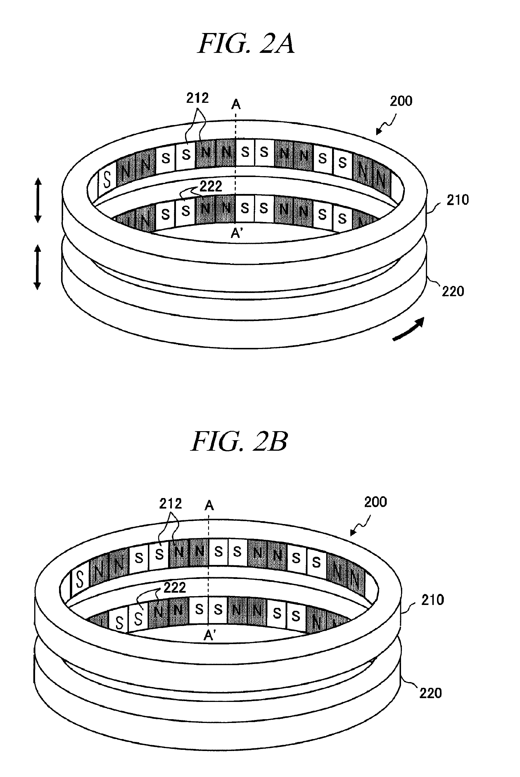
[0020]In accordance with the present disclosure, by rotating magnetic poles of lower magnet ring with respect to the upper magnet ring, a magnetic field perpendicular to a sidewall of a processing chamber can be decreased and a magnetic field parallel to the sidewall can be increased. Accordingly, it is possible to suppress diffusion of plasma over the whole circumference, and, thus, a plasma confining effect by a cusp magnetic field can be increased and uniformity in a substrate process can be improved.

Problems solved by technology

In this case, since a diffusion coefficient of plasma in a diametric direction (in a direction crossing the magnetic field parallel to the sidewall) cannot be reduced sufficiently, the plasma cannot be confined sufficiently.
Accordingly, process uniformity in a central portion and an edge portion of a wafer may be decreased and damage to the sidewall may be caused.

Method used


Image

  • Plasma processing apparatus and plasma processing method
  • Plasma processing apparatus and plasma processing method
  • Plasma processing apparatus and plasma processing method

Examples


Embodiment Construction

[0038]Hereinafter, embodiments of the present invention will be explained in detail with reference to accompanying drawings. Through the present specification and drawings, parts having substantially same function and configuration will be assigned same reference numerals, and redundant description will be omitted.

(Configuration Example of a Plasma Processing Apparatus)

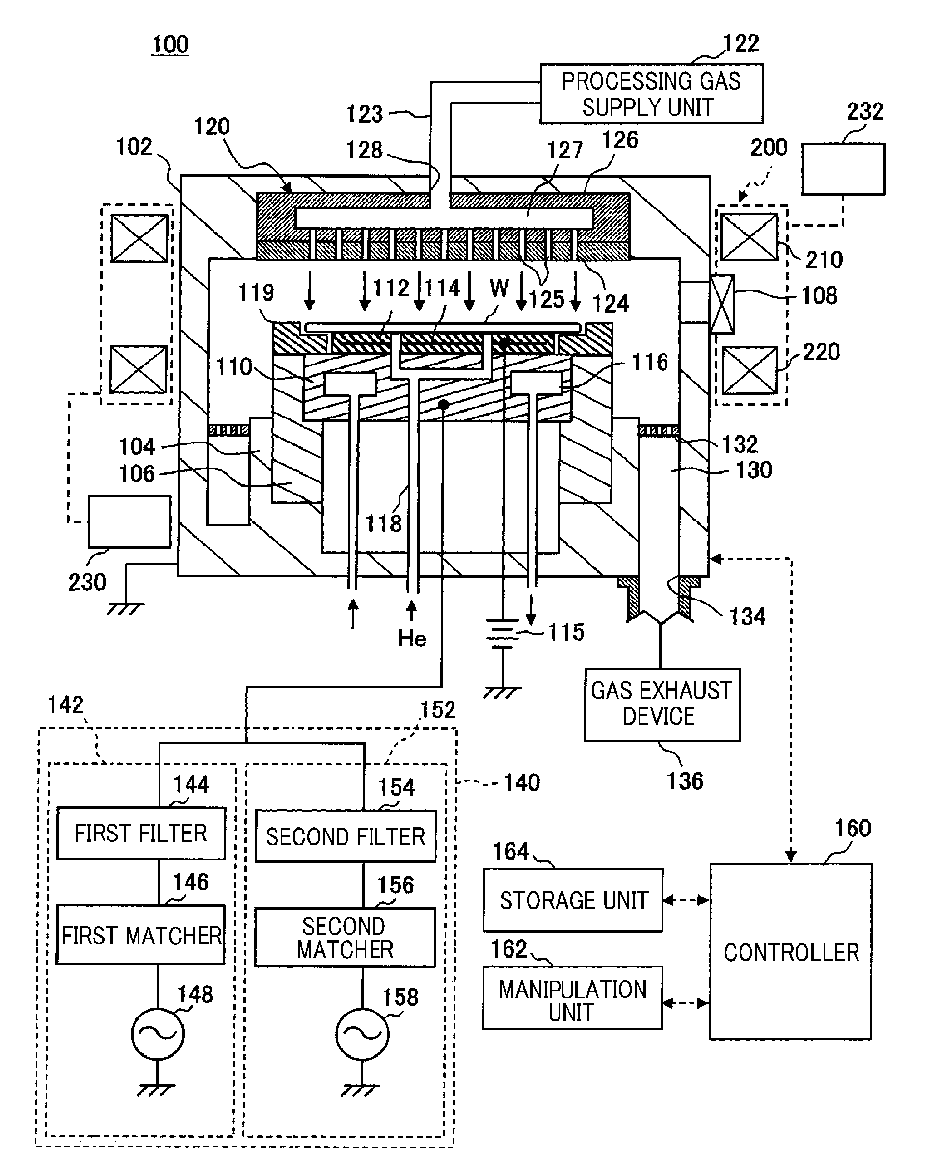
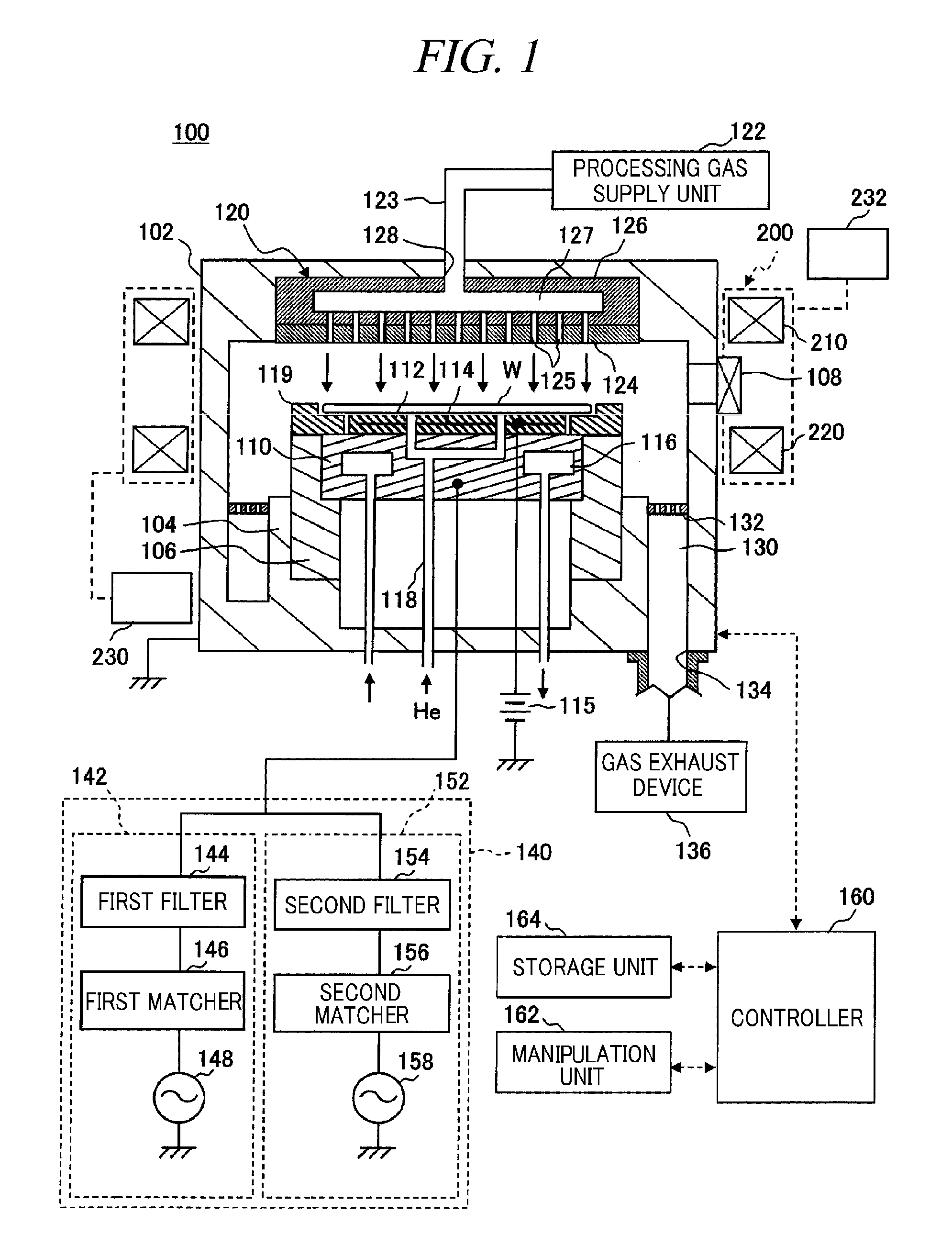
[0039]Above all, a schematic configuration of a plasma processing apparatus in accordance with an embodiment of the present invention will be explained with reference to the drawings. FIG. 1 is a cross sectional view showing a schematic configuration of a plasma processing apparatus in accordance with the present embodiment. Herein, there will be explained a plasma processing apparatus 100 configured as a capacitively coupled (parallel plate type) plasma etching apparatus in which two different high frequencies are applied to a lower electrode (a susceptor).

[0040]The plasma processing apparatus 100 includes a processi...


PUM

PropertyMeasurementUnit
Magnetismaaaaaaaaaa
Plasma poweraaaaaaaaaa

Abstract

Uniformity in a plasma process can be increased by increasing a plasma confining effect by a cusp magnetic field over the whole circumference. There is provided a plasma processing apparatus which performs a process on a substrate by generating plasma of a processing gas in a depressurized processing chamber. The apparatus includes a magnetic field generation unit 200 including two magnet rings 210 and 220 vertically spaced from each other and arranged along a circumferential direction of the processing chamber. Each of the magnet rings includes multiple segments 212 and 222 of which magnetic poles are alternately reversed two by two along a circumferential direction of an inner surface of the magnet ring. In the magnetic field generation unit 200, arrangement of upper and lower magnetic poles is changed by rotating the lower magnet ring 220 in a circumferential direction with respect to the upper magnet ring 210.

Description

CROSS-REFERENCE TO RELATED APPLICATION[0001]This application claims the benefit of Japanese Patent Application No. 2009-206890 filed on Sep. 8, 2009 and U.S. Provisional Application Ser. No. 61 / 252,196 filed on Oct. 16, 2009, the entire disclosures of which are incorporated herein by reference.FIELD OF THE INVENTION[0002]The present disclosure relates to a plasma processing apparatus and a plasma processing method that perform a process on a substrate such as a semiconductor wafer, a FPD (Flat Panel Display) substrate, a solar cell substrate by generating plasma in a processing chamber.BACKGROUND OF THE INVENTION[0003]When a plasma process such as sputtering, etching, and film formation is performed on a substrate such as a semiconductor wafer (hereinafter, simply referred to as “wafer”), there has been used a plasma processing apparatus which generates a cusp magnetic field surrounding plasma in a processing chamber in order to perform a uniform process on a process surface of the ...

Claims


Application Information

Patent Timeline
IPC IPC(8): C23F1/00H01L21/306C23C14/34C23C14/00C23F1/08C23C16/44B05C11/00C23C16/52
CPCH01J37/32623H01L21/31116H01J37/3266
Inventor MATSUYAMA, SHOICHIRO
Owner TOKYO ELECTRON LTD
Learn More