
Control device for controlling the angular setting of a rotor blade of a wind power plant and wind power plant

a technology of angular setting and control device, which is applied in the direction of propellers, water-acting propulsive elements, propulsive elements, etc., can solve the problems of transmitter cables being damaged or even separated, system energy consumption is high, and the operation needs to be maintained

Inactive Publication Date: 2013-01-31
KARL E BRINKMANN GMBH
View PDF13 Cites 17 Cited by
  • Summary
  • Abstract
  • Description
  • Claims
  • Application Information

AI Technical Summary

Benefits of technology

The present invention allows for continued operation even if a motor winding or one of the pitch means fails. This is different from known plants where a failure in one component causes the entire system to shut down.

Problems solved by technology

To implement such pitch control, additional technical effort is needed since an adjustment mechanism for the rotor blades has to be incorporated in the rotor hub.
Thus, the pitch system is that the decisive power limitation and brake system as well safety system of a wind energy plant.
By chunks of ice formed in the rotor blades, transmitter cables can be damaged or even separated.
Such drive systems necessitate a lot of energy for this relatively short time for adapting the rotor blade position.
Such a redundant system is particularly suitable for high power turbines and / or offshore turbines where maintenance and replacement operations are particularly expensive.

Method used


Image

  • Control device for controlling the angular setting of a rotor blade of a wind power plant and wind power plant
  • Control device for controlling the angular setting of a rotor blade of a wind power plant and wind power plant
  • Control device for controlling the angular setting of a rotor blade of a wind power plant and wind power plant

Examples


Embodiment Construction

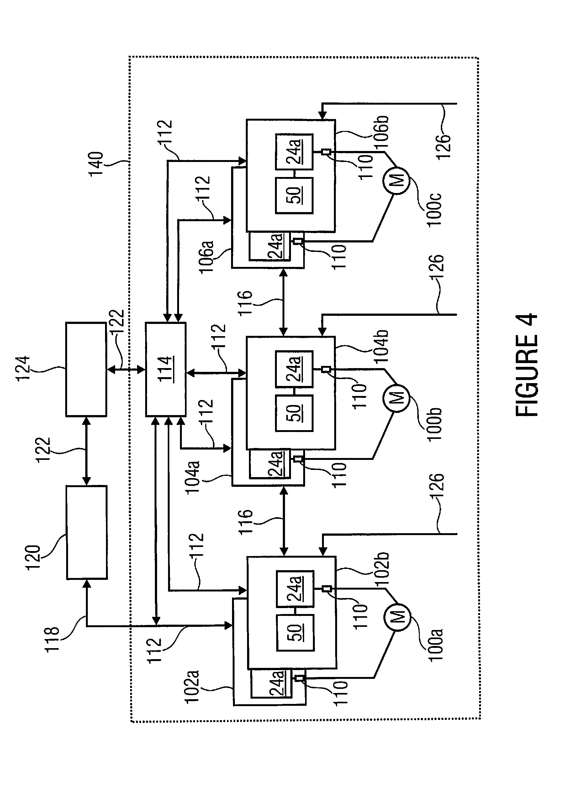
[0040]FIG. 4 shows a control device that is implemented to control the angular setting of three rotor blades of a wind energy plant. However, it is obvious that alternative embodiments can be implemented to control the angular setting of another number of rotor blades, for example two or four rotor blades.

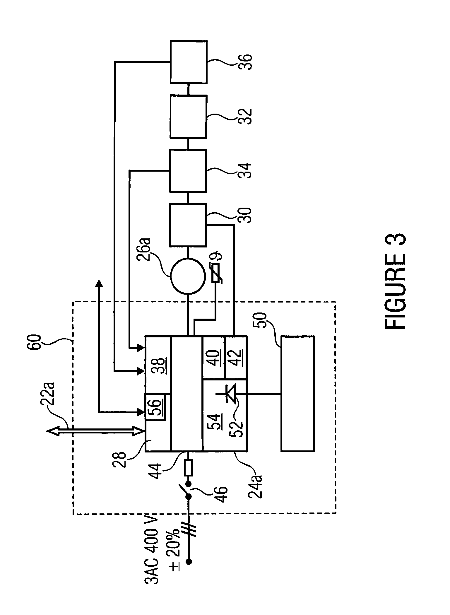
[0041]A drive motor 100a, 100b and 100c is provided for each rotor blade (not shown in FIG. 4). Each of the drive motors 100a-100c has two galvanically isolated exciter windings such that the respective drive motor can be driven by both or only one of the two windings. Each of the exciter windings of motors 100a-100c is coupled to an associated pitch means 102a, 104a, 102b, 104b, 106a, 106b. The pitch means can essentially have a structure and function as described above with reference to FIG. 3. More accurately, each of the pitch means comprises frequency converter (pitch converter) 24a and energy storage 50, for example in the form of ultra capacitor modules. Each of the frequenc...


PUM


Abstract

A control device that is implemented to control an angular setting of a rotor blade of a wind power plant includes a drive motor including first and second windings that are galvanically isolated from one another, wherein the drive motor can be driven by both or only one of the first and second windings to change an angular setting of the rotor blade relative to the hub on which the rotor blade is mounted. Separate pitch controllers including separate frequency converters and separate emergency power supplies are implemented to provide the windings with drive signals. A wind power plant includes a respective controller for each of a plurality of rotor blades mounted on a hub. The pitch controllers provide a redundant system allowing control of the angular setting of a rotor blade of a wind power plant even when one of the pitch controllers for the drive motor has failed.

Description

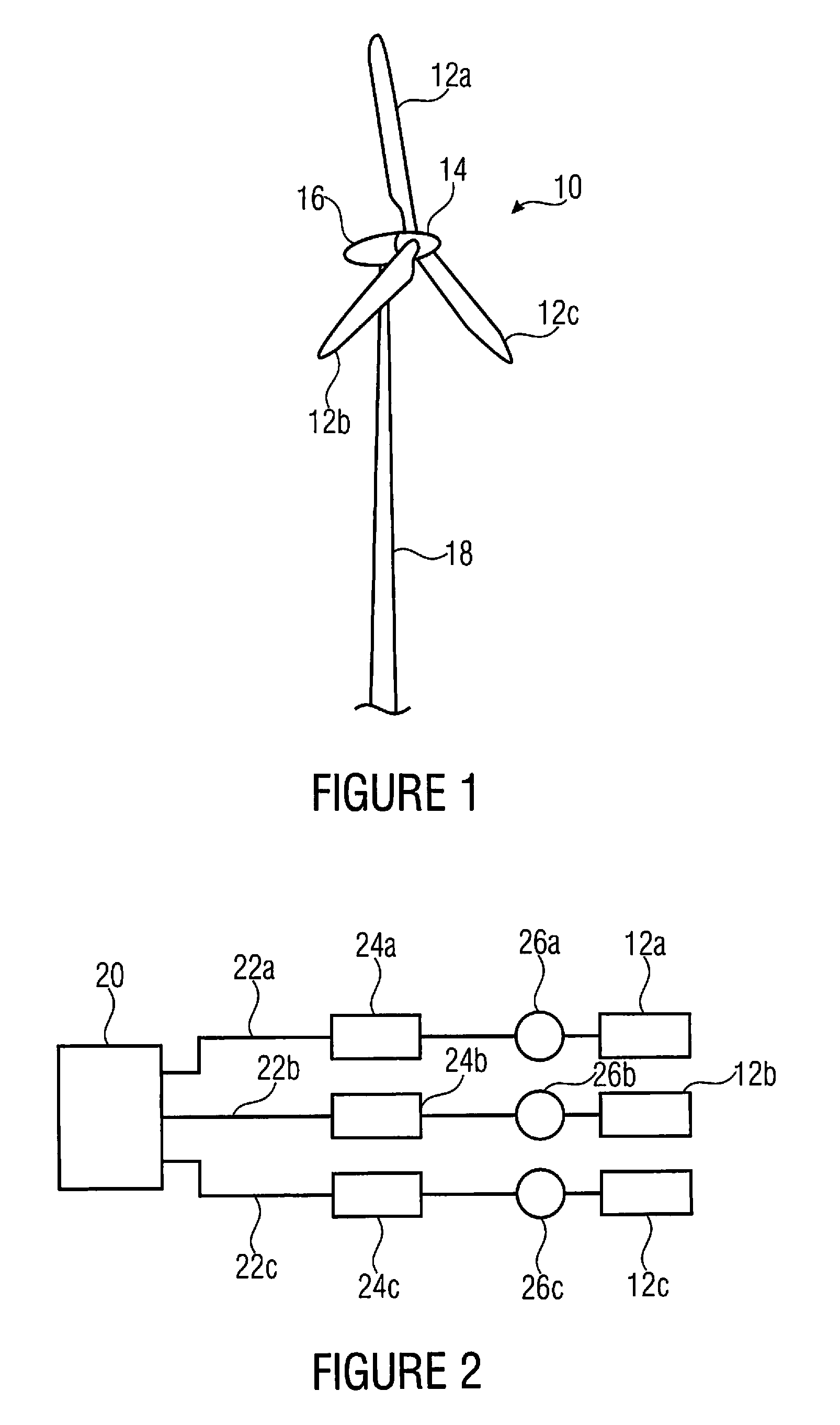
CROSS-REFERENCE TO RELATED APPLICATIONS[0001]This application claims priority from German Patent Application No. 102011079939.7, which was filed on Jul. 27, 2011, and is incorporated herein in its entirety by reference.BACKGROUND OF THE INVENTION[0002]The present invention relates to a control device that is implemented to control an angular setting of a rotor blade of a wind power plant and a wind power plant having a respective control device.[0003]A wind power plant converts kinetic wind energy into electric energy and normally feeds the same into the power supply network. This takes place in that the kinetic energy of the wind flow acts on the rotor blades, such that the rotor is placed into a rotational movement. The rotor passes the rotational energy on to a generator where the same is converted into electric energy.[0004]FIG. 1 shows a schematic illustration of a wind power plant or wind energy plant and comprises a rotor 10 having three rotor blades 12a, 12b and 12c which ar...

Claims


Application Information

Patent Timeline
Patent Type & Authority Applications(United States)
IPC IPC(8): F03D7/02
CPCF03D7/0224Y02E10/723Y02E10/721Y02E10/72
Inventor KOEHNKE, ANDRESCHAEFERFRANZ, RUVEN
Owner KARL E BRINKMANN GMBH
Learn More