Eureka AIR delivers breakthrough ideas for toughest innovation challenges, trusted by R&D personnel around the world.

Developer support member, electrophotographic process cartridge and electrophotographic image forming apparatus

a technology of development support and development support, which is applied in the direction of electrographic process, instruments, transportation and packaging, etc., can solve the problems of insufficient improvement of topical reduction of roller surface roughness, inability to produce uniform images, and inability to achieve uniform output. uniform

Active Publication Date: 2013-01-31
CANON KK
View PDF1 Cites 27 Cited by
  • Summary
  • Abstract
  • Description
  • Claims
  • Application Information

AI Technical Summary

Benefits of technology

The present invention is directed to improving the quality of electrophotographic images formed by developer support members used in high-temperature and high-humidity environments. The invention adds polymeric resin particles to the surface of the developer support member to stabilize the conveying of toner. This results in a smoother surface that prevents any quality degradation of the image upon contact with the regulating blade. The invention provides a stable output of a uniform image even after extended periods of storage in severe weather conditions. It is useful for developing rollers and for obtaining high-quality electrophotographic process cartridges and image forming apparatus.

Problems solved by technology

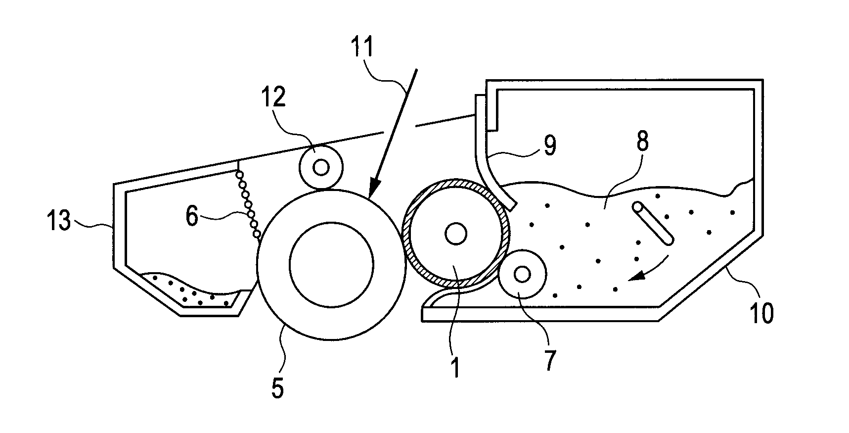
Therefore, an external force applied from the regulating blade deforms the resin particles on the surface of the developer support member positioned on the abutting portion against the regulating blade, and the surface roughness of the developer support member on the abutting portion of the developer support member against the regulating blade is reduced from a predetermined value, thereby sometimes impairing quality of an electrophotographic image.
However, use of the polyurethane resin disclosed in Japanese Patent Application Laid-Open No. 2005-141192 is not sufficient to address a topical reduction in roller surface roughness due to the deformation of the resin particles on the abutting portion against the regulating blade, and thus a uniform image cannot be sometimes output after left to stand for a long period.
In addition, use of the polyurethane resin particles disclosed in Japanese Patent Application Laid-Open No. 2009-116009 also cannot possibly suppress adverse effects under each temperature and humidity environment, and in particular, cannot sufficiently improve a topical reduction in roller surface roughness.

Method used

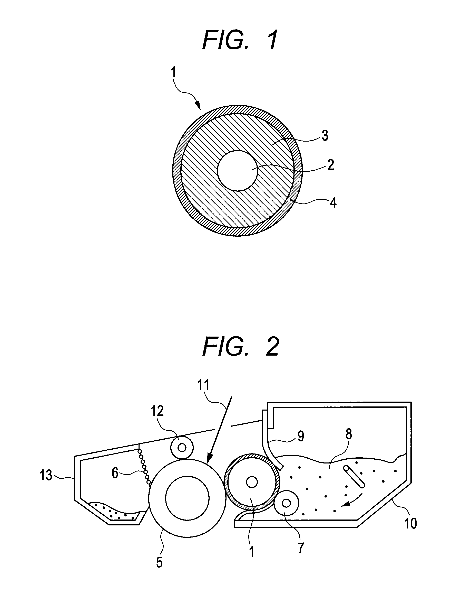
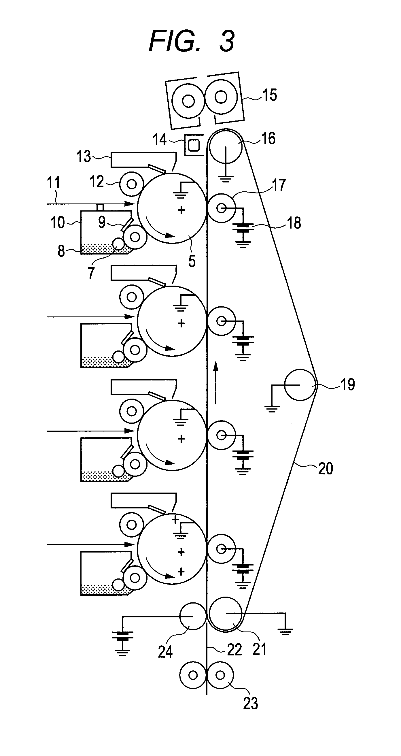

Image

  • Developer support member, electrophotographic process cartridge and electrophotographic image forming apparatus
  • Developer support member, electrophotographic process cartridge and electrophotographic image forming apparatus
  • Developer support member, electrophotographic process cartridge and electrophotographic image forming apparatus

Examples


example 1

[0148]Hereinafter, a method for producing the developing roller of the invention of the present application will be described.

[0149]The isocyanate group-terminal prepolymer B-1 (109 parts by mass based on 100 parts by mass of the polyol A-1), and 30 parts by mass of carbon black MA 230 (trade name, produced by Mitsubishi Chemicals Corporation) relative to a resin component were mixed, dissolved in methyl ethyl ketone and mixed, and uniformly dispersed by a sand mill to obtain a dispersion 1.

[0150]Herein, in order to measure Tg, a small amount of the dispersion 1 was spread to a ceramic plate, heat-treated at 150° C. for 2 hours to thereby prepare a test piece of a polyurethane matrix polymer, and subjected to the measurement of Tg. The Tg was −61° C.

[0151]The polyurethane resin particles C-1 (100 parts by mass relative to a resin component) as the resin particles was added to the above dispersion 1 and stirred by a stirring motor for 10 minutes to obtain a surface layer forming coat...

example 2

[0153]The isocyanate group-terminal prepolymer B-1 (19 parts by mass based on 100 parts by mass of the polyol A-2), and 30 parts by mass of carbon black MA 230 (trade name, produced by Mitsubishi Chemicals Corporation) relative to a resin component were mixed, dissolved in methyl ethyl ketone and mixed so that the total solid content proportion was 30% by mass, and uniformly dispersed by a sand mill to obtain a dispersion 2.

[0154]Herein, in order to measure Tg, a small amount of the dispersion 2 was spread to a ceramic plate, heat-treated at 150° C. for 2 hours to thereby prepare a test piece of a polyurethane matrix polymer, and subjected to the measurement of Tg. The Tg was −58° C.

[0155]The polyurethane resin particles C-1 (100 parts by mass relative to a resin component) as the resin particles was added to the above dispersion 2 and stirred by a stirring motor for 10 minutes to obtain a surface layer forming coating material 2.

[0156]Then, the surface layer forming coating materia...

example 3

[0157]The isocyanate group-terminal prepolymer B-1 (108 parts by mass based on 100 parts by mass of the polyol A-3), and 30 parts by mass of carbon black MA 230 (trade name, produced by Mitsubishi Chemicals Corporation) relative to a resin component were mixed, dissolved in methyl ethyl ketone and mixed, and uniformly dispersed by a sand mill to obtain a dispersion 3.

[0158]Herein, in order to measure Tg, a small amount of the dispersion 3 was spread to a ceramic plate, heat-treated at 150° C. for 2 hours to thereby prepare a test piece of a polyurethane matrix polymer, and subjected to the measurement of Tg. The Tg was −54° C.

[0159]The polyurethane resin particles C-1 (100 parts by mass relative to a resin component) as the resin particles was added to the above dispersion 3 and stirred by a stirring motor for 10 minutes to obtain a surface layer forming coating material 2.

[0160]Then, the surface layer forming coating material 2 was dip coated on the above elastic layer 3 and then d...


PUM


Abstract

A developing roller which is excellent in image quality and image durability and stably outputs a uniform image, and a process cartridge and an electrophotographic apparatus using the developing roller are provided. The developing roller has a mandrel, an elastic layer and a surface layer covering the elastic layer surface, wherein the surface layer contains a urethane resin having at least one structure of the followings A) and B) between two adjacent urethane linkages: A) a structure represented by the following structural formula (1), and at least one structure selected from the group consisting of structures represented by the following structural formulae (2) and (3), and B) a structure represented by the following structural formula (4), and the surface layer contains polyurethane resin particles of which the elastic part of the indentation work based on ISO 14577-1 is 80% or more, is obtained:

Description

CROSS-REFERENCE TO RELATED APPLICATIONS[0001]This application is a continuation of International Application No. PCT / JP2012 / 003167, filed May 15, 2012, which claims the benefit of Japanese Patent Application No. 2011-156960, filed Jul. 15, 2011.BACKGROUND OF THE INVENTION[0002]1. Field of the Invention[0003]The present invention relates to a developer support member and an electrophotographic process cartridge for use in an electrophotographic image forming apparatus, as well as an electrophotographic image forming apparatus.[0004]2. Description of the Related Art[0005]In an electrophotographic image forming apparatus, a photosensitive member (drum) is charged by a charging unit, and an electrostatic latent image is formed on the drum by laser. Then, a developer (toner) in a developing container is conveyed by a developer support member, and the electrostatic latent image on the drum is developed by the toner at the portion of the drum to which the developer support member is close....

Claims


Application Information

Patent Timeline
Patent Type & Authority Applications(United States)
IPC IPC(8): G03G21/16G03G15/08
CPCG03G15/0818B60C1/0016B60C2011/0025B60C11/005
Inventor KOYANAGI, TAKASHIYAMADA, MASAKIKAWAMURA, KUNIMASASAKURAI, YUJI
Owner CANON KK
Why Eureka
Eureka Blog
Learn More