
Optically Stimulated Luminescence Radiation Measurement Device

a luminescence radiation and measurement device technology, applied in the direction of material analysis, luminescent dosimeters, instruments, etc., can solve the problems of difficult to achieve, difficult to ensure, and difficult to reliably provide electrical power and complex electronic circuits downhole, so as to improve reliability and accuracy of radiation measurement devices

Inactive Publication Date: 2013-01-17
SCHLUMBERGER TECH CORP
View PDF6 Cites 7 Cited by
  • Summary
  • Abstract
  • Description
  • Claims
  • Application Information

AI Technical Summary

Benefits of technology

The present invention is a radiation measuring device that uses an optically stimulated luminescence material to accumulate radiation over a set period of time. This allows the device to "remember" nuclear events and provides a flexible way to measure radiation levels over time. The device can be operated remotely without any permanent power or in-situ electronics, making it reliable and accurate even in harsh conditions. Its unique design features a passive sensor that is power and maintenance free.

Problems solved by technology

Providing electrical power and complex electronic circuits downhole to reliably measure radiation for a long period of time, for example in permanent reservoir monitoring application, is often difficult to achieve due to the harsh environment affecting the electronic circuit's dependability, and due to the lack of available space to store batteries having an adapted capacity and a lifetime compliant with said application.
Moreover, such electronic circuits and batteries are costly and subject to maintenance in order to maintain the measurement accuracy and limit failures.

Method used


Image

  • Optically Stimulated Luminescence Radiation Measurement Device
  • Optically Stimulated Luminescence Radiation Measurement Device
  • Optically Stimulated Luminescence Radiation Measurement Device

Examples


Embodiment Construction

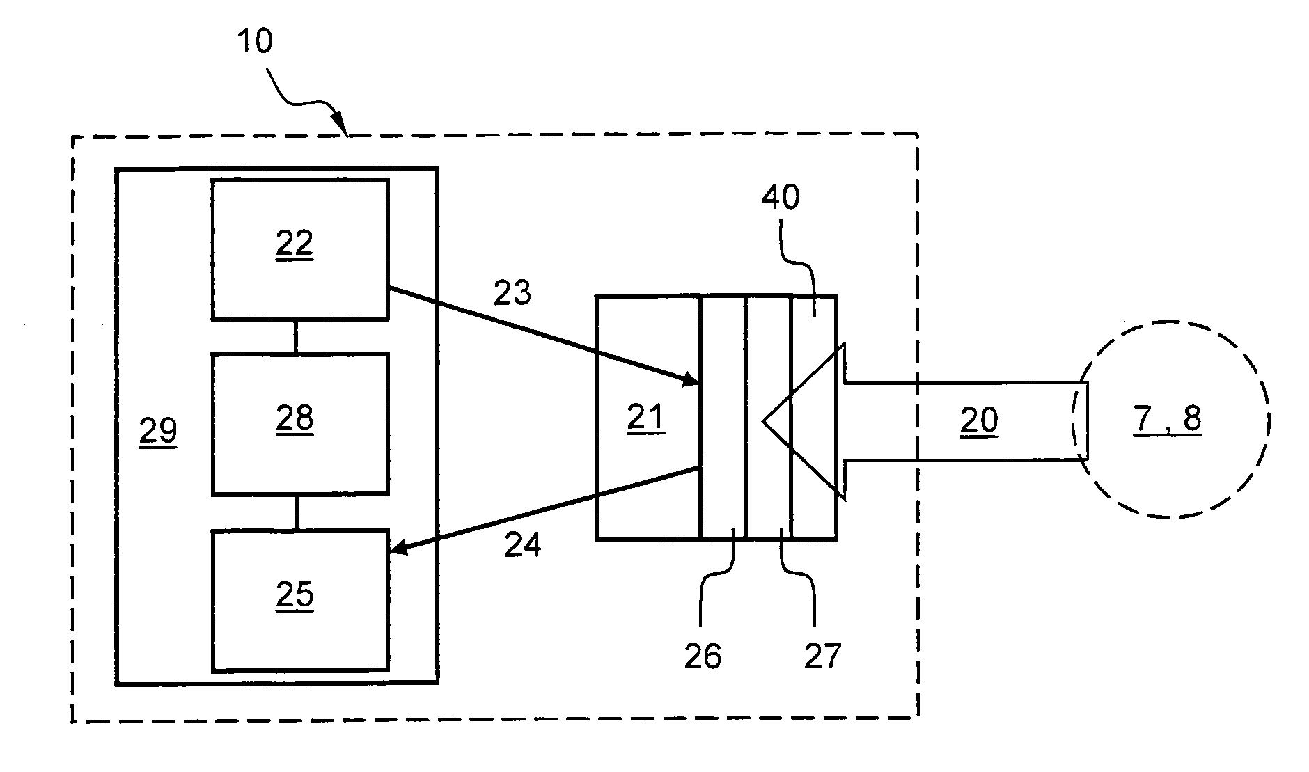
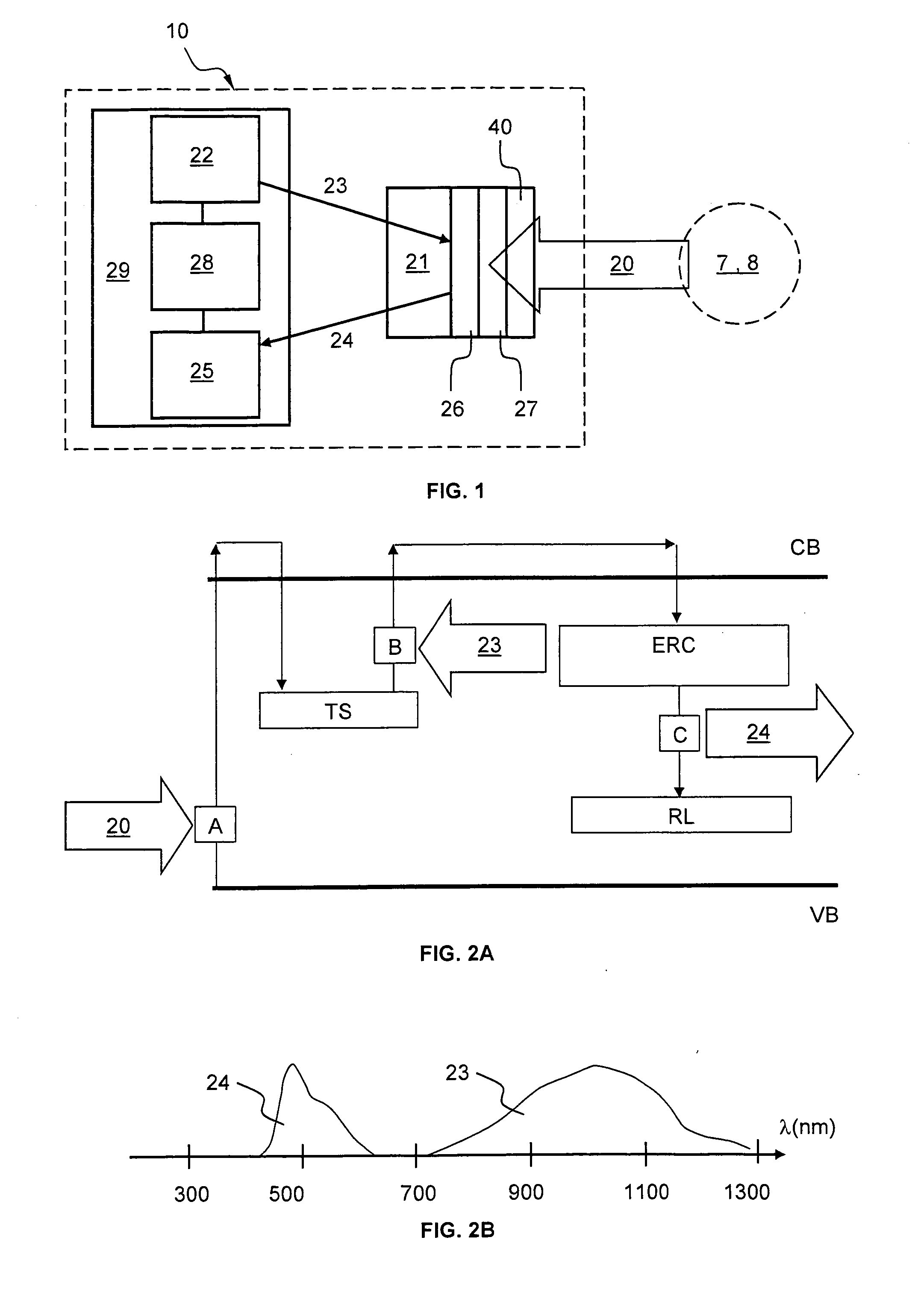
[0039]FIG. 1 schematically shows an embodiment of a device to measure radiation in a well drilled in a geological formation. In a preferred embodiment, the radiation measuring device comprises a sensing arrangement 21 for sensing radiation, and an operating arrangement 29 for controlling the operation of the sensing arrangement 21.

[0040]The sensing arrangement 21 comprises an optically stimulated luminescence material 26. The sensing arrangement 21 has been positioned in an environment where radiation 20 is to be measured over a defined accumulation delay. More precisely, the optically stimulated luminescence material 26 has been positioned near a zone of interest 7, 8 such as to accumulate radiation 20 emitted by said zone of interest 7, 8 over said delay.

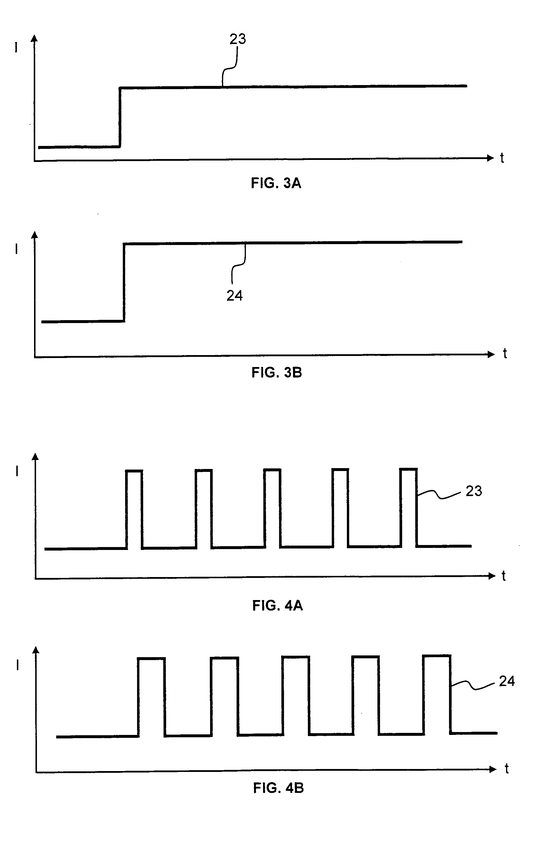
[0041]The operating arrangement 29 comprises a light source 22, a light sensor 25 and a processing unit 28. The light source 22 may submit the sensing arrangement 21 to a stimulation light 23. The stimulation light 23 optically st...


PUM


Abstract

A device is presented to measure radiation in a well drilled in a geological formation. The device comprises at least one sensing arrangement, a light source, and a light sensor. The sensing arrangement comprises an optically stimulated luminescence material arranged to be positioned near a zone of interest such as to accumulate radiation emitted by the zone of interest over a defined accumulation delay. The light source is arranged to optically stimulate emission of a luminescence light by the sensing arrangement with a stimulation light according to a first wavelength range. And the light sensor is arranged to measure the luminescence light emitted by the sensing arrangement according to another wavelength range, a measured intensity of the luminescence light related to the accumulated radiation.

Description

TECHNICAL FIELD[0001]An aspect of the present invention relates to a device using optically stimulated luminescence to measure radiation. The optically stimulated luminescence radiation measuring device may be used in oilfield related applications, for example, to measure radiation of a geological formation surrounding a well that has been drilled for the purpose of hydrocarbon exploration and production.BACKGROUND OF THE INVENTION[0002]It is known to measure ionizing radiation like gamma-ray with a Geiger counter or a spectrometer. Typically, a spectrometer comprises an energy-sensitive radiation detector (sodium iodide NaI scintillation counter or a high-purity germanium detector), a pulse sorter, amplifiers, and measurement processing unit. This requires electronic components and electrical power at the location where the measurements are performed. In oilfield related applications, such radiation measuring devices must be placed downhole to measure the radiation emitted by the g...

Claims


Application Information

Patent Timeline
IPC IPC(8): G01V5/06
CPCG01T1/10G01N21/6402G01V5/06
Inventor SAENGER, RICHARD G.
Owner SCHLUMBERGER TECH CORP
Learn More