
Method for Automatic Optimization Of Liquid Chromatography Autosampler

a liquid chromatography and autosampler technology, applied in the field of automatic optimization of liquid chromatography autosamplers, can solve the problems of limited fluid-routing flexibility and limited ability to change solvents, direct influence of sample transportation, and difficulty in determining beforehand the duration of an autosampler procedure, so as to minimize the risk of losing or damaging a sample, the risk of holding the temperature of or otherwise excessively handling a sensitive sample is minimized, and the risk of losing or damaging

Active Publication Date: 2013-01-17
THERMO FINNIGAN
View PDF1 Cites 26 Cited by
  • Summary
  • Abstract
  • Description
  • Claims
  • Application Information

AI Technical Summary

Benefits of technology

The present invention is a system that reduces the risk of damaging or losing samples during transportation in an autosampler system. It also minimizes variations in the time a sample is held in a single channel system, reducing the risk of excessive handling. In a multiplexed system, the invention automatically optimizes the efficiency of multiplexing while maintaining flexibility and robustness.

Problems solved by technology

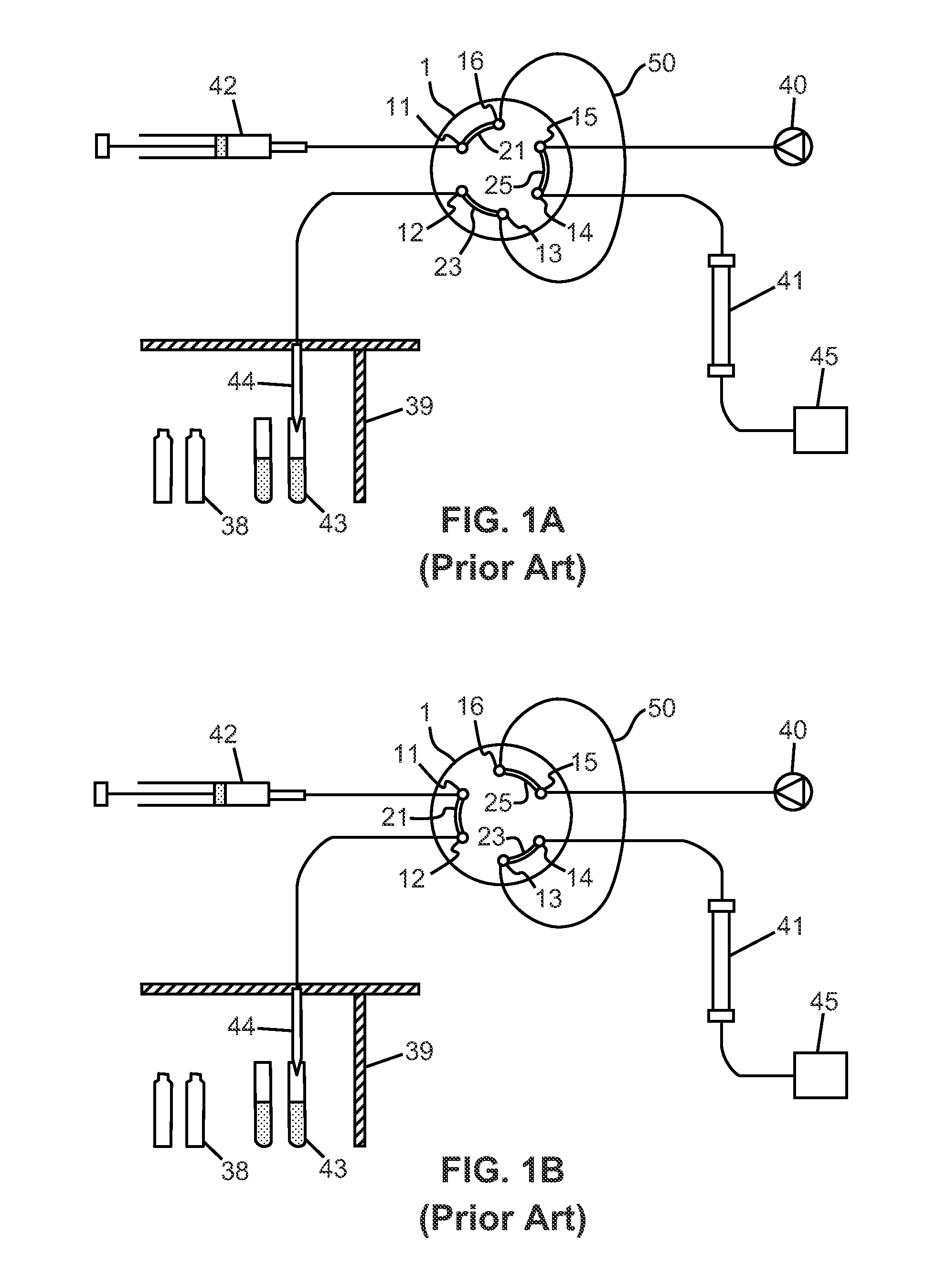
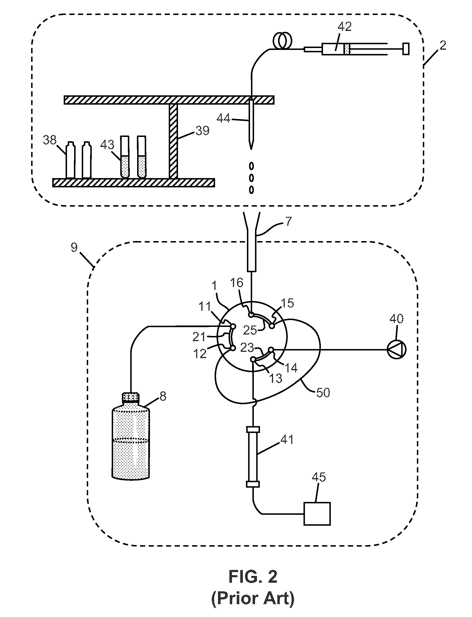
Auto-injectors commonly mimic cumbersome manual injection methods in which a metered aliquot of a sample is aspirated from a desired sample reservoir into a transfer tubing loop under the action of a syringe pump.
The auto-injector systems illustrated in FIGS. 1-2 are basic systems which provide limited fluid-routing flexibility and limited ability to change solvents during the course of a separation.
Unlike operational procedures run by other components, such as pumps and detectors, it is often difficult to determine beforehand the duration of an autosampler procedure.
Any issue encountered during this phase may directly affect the sample being transported.
Possible problems which may occur during this phase may include leakage of a sample out of a sample needle (for low-viscosity samples), sample evaporation or time-dependent degradation of the sample, either by exposure of the sample to air, to an unfavorable temperature environment or to ambient light.
Since the robot operations may require a time period of 1-3 minutes whereas the sample analyses may require substantially longer periods—for instance 4-12 minutes, this so called “Look-Ahead” methodology, may frequently lead to situations in which an autosampler has completed steps prior to injection and thus spends a significant period of time waiting for the “System Sync” to continue.
The existence of such waiting periods can have several negative consequences: (i) samples sensitive to temperature or other factors may be affected by the length of time spent in the syringe and also by the potential time variations seen between samples; (ii) samples with very low viscosity may begin to drip or mix across air gaps; and (iii) the probability of losing a sample due to an abort or error of a previous sample is increased.
Such delays in the operation of the LC system can lead to overall analytical inefficiency which can become significant during the running of numerous samples of a batch.
Failure to make such adjustments can seriously affect multiplexing timing efficiency and, as noted above, can effect overall system efficiency or can cause degradation or loss of samples.
Such automated screening systems are frequently designed for unattended or overnight operation with little operator intervention other than initial loading of samples.
In such systems, ample containers may be accessed in a “random” fashion which is generally unpredictable to a user—as may be the case of the sample access and analysis operations are under the control of a computerized scheduler, as may occur with multiplexed chromatographic systems.
Because of these factors, it may be difficult or impossible, in practice, for a user to manually maintain detailed logs of elapsed autosampler times for different sample types or procedures.

Method used


Image

  • Method for Automatic Optimization Of Liquid Chromatography Autosampler
  • Method for Automatic Optimization Of Liquid Chromatography Autosampler
  • Method for Automatic Optimization Of Liquid Chromatography Autosampler

Examples


Embodiment Construction

[0040]The following description is presented to enable any person skilled in the art to make and use the invention, and is provided in the context of a particular application and its requirements. Various modifications to the described embodiments will be readily apparent to those skilled in the art and the generic principles herein may be applied to other embodiments. Thus, the present invention is not intended to be limited to the embodiments and examples shown but is to be accorded the widest possible scope in accordance with the features and principles shown and described. To appreciate the features of the present invention in greater detail, please refer to FIGS. 1-8 in conjunction with the following discussion.

[0041]FIG. 6 is a schematic illustration of a preferred control software architecture for implementing methods in accordance with the present teachings. The modular software architecture system 203 illustrated in FIG. 6 is useful for—but not limited to—control of the ope...


PUM


Abstract

An method for optimizing operation of an autosampler coupled to a liquid chromatography (LC) system comprises: reading, from electronic memory storage, a pre-injection time corresponding to the time required for the autosampler to perform operations preparatory to injecting a sample; calculating an autosampler delay time from the pre-injection time and from a sample analysis time; performing the autosampler operations preparatory to injecting the sample after delaying said autosampler operations for the autosampler delay time; measuring a time value for the preceding performing of autosampler operations; replacing the pre-injection time value stored on the electronic memory storage with the measured time value for the preceding performing of autosampler operations if the measured value is greater than the pre-injection time value stored on the electronic memory storage; and injecting the sample from the autosampler into the LC system after receipt of a signal from the LC system by the autosampler.

Description

TECHNICAL FIELD[0001]This invention pertains generally to liquid chromatography, and more particularly to methods for automatically operating an apparatus for delivering samples of liquid to be analyzed in a liquid chromatographic column.BACKGROUND OF THE INVENTION[0002]In liquid chromatography, a compound is broken down into its components in a chromatographic column, so that these components can be further processed or analyzed by a detector, such as a mass spectrometer. In various liquid chromatography techniques, such as High-Pressure Liquid Chromatography (HPLC), the components of a sample to be separated or analyzed are dissolved in a mobile phase liquid, termed an eluent, and then conveyed by that liquid to a stationary phase within one or more chromatography columns. HPLC analyses are employed in a wide variety of applications, such as drug discovery and development, environmental testing, and diagnostics. In HPLC systems, the chromatographic columns are interconnected to ot...

Claims


Application Information

Patent Timeline
IPC IPC(8): G01N30/02
CPCG01N30/24
Inventor MARKS, AARON N.
Owner THERMO FINNIGAN
Learn More