Osteoimplants and Methods for their Manufacture
a technology of osteoimplants and bone marrow, which is applied in the direction of joint implants, manufacturing tools, prostheses, etc., can solve the problems of requiring preparation, affecting the quality of bone marrow,
- Summary
- Abstract
- Description
- Claims
- Application Information
AI Technical Summary
Benefits of technology
Problems solved by technology
Method used
Image
Examples
example 1
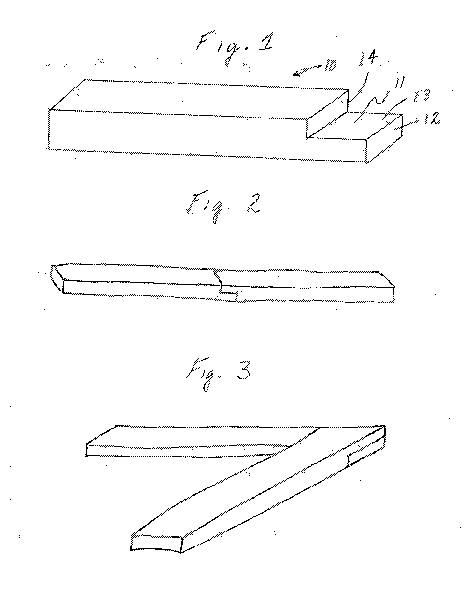
[0083]This example illustrates the preparation of an osteoimplant of the invention in the form of the generally rectangular strip shown in FIG. 1. Osteoimplant 10 possesses a tab 11 of step-like configuration which facilitates combining like strips as shown in FIGS. 2 and 3. Tab 11 includes a first face 12, a flat surface 13 and a second face 14. In general, the osteoimplant can possess a length (inclusive of tab 11) of from about 2 cm to about 50 cm and preferably from about 5 cm to about 20 cm, a width of from about 0.2 cm to about 5 cm, and preferably from about 0.5 cm to about 3 cm, and a depth of from about 0.2 cm to about 2.0 cm, and preferably from about 0.5 cm to about 1.0 cm, with a ratio of length to width of from about 1 to about 5, preferably from about 1 to about 10 and most preferably from about 1 to about 20. Specific dimensions of osteoimplant 10 are a length (inclusive of tab 11) of 10 cm or 20 em, a width of 1.0 cm, a height of 0.8 cm, a height of 0.4 cm for each o...
example 2
[0086]This example illustrates the preparation of a putty-like, easily moldable osteoimplant to composition in accordance with the invention.
[0087]Approximately 200 g to about 300 g of the elongate bone particles used in making the strip-configured osteoimplant of Example 1 are uniformly combined with from about 5 ml to about 15 ml of glycerol per gram of elongate bone particles and from about 5 mls to about 20 ml of distilled deionized water per grant of elongate bone particles to form a slurry which is permitted to swell and hydrate over a period of from 1 to 8 hours. Optionally, prior to either the addition of glycerol, water or both, the elongate fibers may be grated or shredded to reduce any one or more of their overall dimensions. A further optional treatment would be to knead blend, grind or shred the elongate fibers after the addition of glycerol, water or both. Excess liquid is drained from the slurry and the mixture is thereafter lyophilized under conventional lyophilizati...
example 3
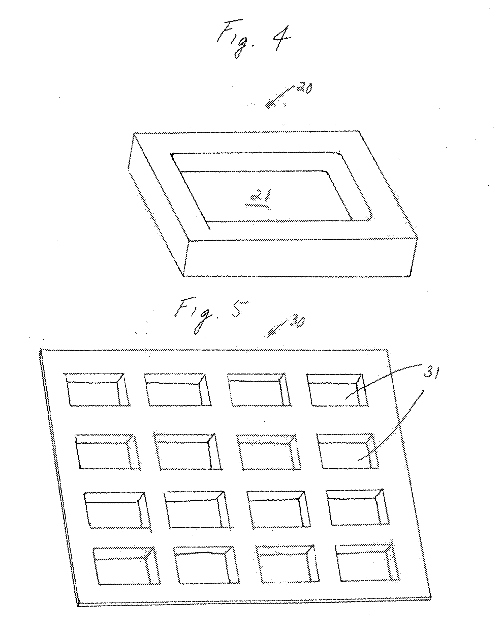
[0088]This example illustrates the manufacture of the trough-like osteoimplant 20 shown in FIG. 4. Osteoimplant 20 possesses a generically rectangular shape and features a trough-like rectangular depression 21. A quantity of such osteoimplants can be conveniently formed using form 30 shown in FIG. 5, cassette 40 shown in FIG. 6 and lid 50 shown in FIG. 7.
[0089]A shiny of swollen, hydrated &mineralized elongated bone particles in glycerol and water prepared as described in Example 2 is introduced into cassette 40 of FIG. 6. The perforated base of the cassette permits excess liquid to drain from the slurry. A molding surface in the form of sheet 30 of FIG. 5 having little or no adhereney for the slurry and possessing depressions 31 is than impressed upon the exposed surface of the slurry with the application of a gentle amount of pressure so as to provide a molded sheet of substantially uniform thickness (from about 0.5 cm to about 1.0 cm) possessing depressions conforming to the depr...
PUM
 Abstract
Description
Claims
Application Information
 - R&D
- Intellectual Property
- Life Sciences
- Materials
- Tech Scout
- Unparalleled Data Quality
- Higher Quality Content
- 60% Fewer Hallucinations
Browse by: Latest US Patents, China's latest patents, Technical Efficacy Thesaurus, Application Domain, Technology Topic, Popular Technical Reports.
© 2025 PatSnap. All rights reserved.Legal|Privacy policy|Modern Slavery Act Transparency Statement|Sitemap|About US| Contact US: help@patsnap.com


