Fiber fuse terminator

a fiber fuse terminator and fiber laser technology, applied in the direction of optics, instruments, optical elements, etc., can solve the problems of considerable loss at a portion, difficult to reduce splicing loss, and high cost, and achieve low cost, low splicing loss, and prevent damage to transmission equipment

Inactive Publication Date: 2013-01-10
FUJIKURA LTD
View PDF1 Cites 0 Cited by
  • Summary
  • Abstract
  • Description
  • Claims
  • Application Information

AI Technical Summary

Benefits of technology

The present invention is about a device that can prevent damage to optical equipment when a fiber fuse occurs. It is affordable to manufacture and can be easily connected to optical fibers, which can increase the transmission capacity and laser output.

Problems solved by technology

However, conventional technologies have the following problems.
In the technique described in Patent Document 1 (method of terminating the fiber fuse by expanding the MFD of a part of the SMF), it is difficult to reduce the splicing loss between the optical fiber of which the MFD is expanded and a general SMF.
In order to reduce the splicing loss between the optical fiber of which the MFD is expanded and the general SMF, there is a need to diffuse a dopant in the core of the SMF in a tapered shape, or to prepare various types of optical fibers having different MFDs and splice them in multiple stages; this is extremely expensive.
In the technique described in Patent Document 2 (method of terminating the fiber fuse by inserting the GI fiber), there is a problem of considerable loss at a portion where the light is combined between the GI fiber and the SMF.
In order to reduce the loss, it is necessary to enlarge the diameter of the light entering from the SMF by providing a GI fiber portion having a length of ¼ of a pitch so as to reduce the power density of the light, and then, to reduce the diameter of the light by again providing a GI fiber portion having a length of ¼ of a pitch, thereby allowing the light to enter the next SMF; this configuration is complex and expensive.

Method used


Image

  • Fiber fuse terminator
  • Fiber fuse terminator
  • Fiber fuse terminator

Examples


first embodiment

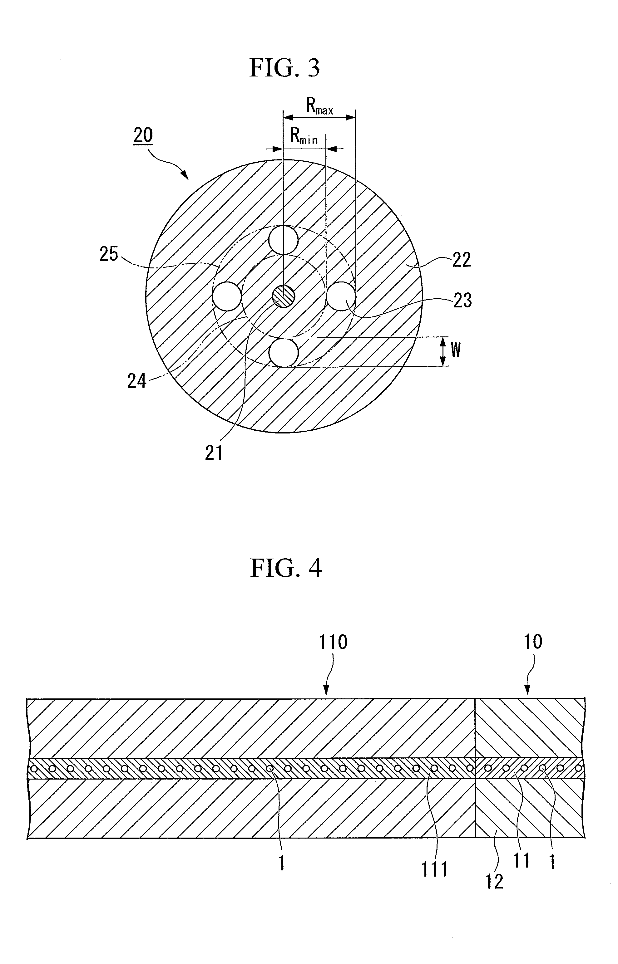
[0062]As shown in FIG. 3, a fiber fuse terminator according to a first embodiment of the present invention is constituted by an optical fiber (hereinafter, referred to as “hole-assisted optical fiber”) 20 which includes a core 21 having no holes and a cladding 22 with a plurality of holes 23 (4 holes in this embodiment) which are disposed so as to extend in a longitudinal direction, and in which the refractive index of the core 21 is higher than that of a portion of the cladding 22 excepting portions of the holes 23.

[0063]In the hole-assisted optical fiber 20 shown in FIG. 3, the holes 23 in one layer are provided in the cladding 22 so as to surround the core 21.

[0064]In this embodiment, it is possible to use the hole-assisted optical fiber 20 as a fiber fuse terminator by properly setting the ratio between the mode field diameter of the hole-assisted optical fiber 20 at a used wavelength and the distance from the center of the fiber 20 to the hole 23, the ratio between the mode fie...

second embodiment

[0108]A fiber fuse terminator according to a second embodiment of the present invention will be described in the following. The second embodiment is different from the first embodiment in that the holes are provided in a plurality of layers. The same components as those of the first embodiment are designated by the same reference numerals, and the description thereof will be omitted.

[0109]As shown in FIG. 11, the fiber fuse terminator according to this embodiment is constituted by an optical fiber (hereinafter, referred to as “hole-assisted optical fiber”) 20A which includes a core 21 having no holes and a cladding 22 with a plurality of holes 23 (60 holes in this embodiment) which are disposed so as to extend in a longitudinal direction, and in which the reflactive index of the core 21 is higher than that of a portion of the cladding 22 excepting portions of the holes 23.

[0110]In addition, in the hole-assisted optical fiber 20A shown in FIG. 11, the holes 23 are provided in a plura...

example 1

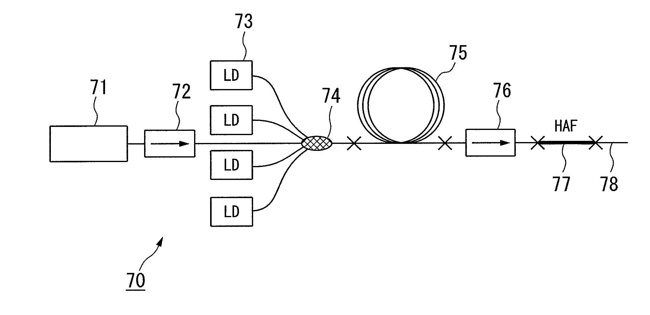
[0147]The HAF (Fiber A) having the cross section shown in FIG. 9 is used as the optical fiber 55 to be measured, and Experiments 1-1 and 1-2 were performed by changing the incident power.

[0148]The experiment numbers 1-1 and 1-2 in Table 1 show the parameters of Fiber A and the experiment conditions. As for Fiber A, the cladding diameter Dfiber is 125 μm, the number of the holes is 6, Rmin is 8.5 μm, W is 7.3 μm, Rmax is 15.8 μm, and the MFD at the wavelength of 1.55 μm is 10.2 μm. In addition, 2×Rmin / MFD is 1.67.

[0149]As for Fiber A, when the incident wavelength is 1.55 μm, and when the incident power is 9.8 W (experiment number 1-1) and when the incident power is 3.0 W (experiment number 1-2), the terminating performance of the fiber fuse was investigated. In both Experiments 1-1 and 1-2, the value of 2×Rmin / MFD is 1.67, which is in a range no less than 1.2 and no more than 2.1. The value of W / MFD is 0.72, which is no less than 0.3. In addition, since the value of W is 7.3 μm and t...


PUM


Abstract

A fiber fuse terminator which is used to terminate a fiber fuse, comprising: an optical fiber which includes a core and a cladding having holes extending in a longitudinal direction thereof, in which: a refractive index of the core of the optical fiber is higher than a refractive index of a portion of the cladding excepting portions of the holes; when it is assumed that a mode field diameter at a used wavelength of the optical fiber is MFD, and a distance in a cross section perpendicular to the longitudinal direction of the optical fiber between a center of the core and a position, closest to the center of the core, of the hole that is closest to the core is Rmin, a value expressed by 2×Rmin / MFD is no less than 1.2 and no more than 2.1; when it is assumed that a width, in a diameter direction, of a region where the holes present in the cladding is W, a value expressed by W / MFD is no less than 0.3; and when it is assumed that a diameter of the cladding of the optical fiber is Dfiber, W≦0.45×Dfiber is satisfied.

Description

CROSS-REFERENCE TO RELATED APPLICATIONS[0001]This is a divisional of application Ser. No. 12 / 728,903, filed Mar. 22, 2010 which priority is claimed on Japanese Patent Application No. 2008-216485, filed Aug. 26, 2008, which is a national stage of PCT / JP2009 / 004101, filed Aug. 25, 2009 the contents of which are incorporated herein by reference.TECHNICAL FIELD[0002]The present invention relates to a fiber fuse terminator, fiber laser, and an optical transmission line, which can terminate a fiber fuse in an optical transmission line, a light filter laser, and the like through which high-power light is propagated, and can prevent damage to transmission equipment, a light source, and the like.BACKGROUND ART[0003]In recent years, in the field of optical communications, as transmission capacity increases, the intensity (power) of light which is propagated in optical fibers increases. In addition, in optical fiber lasers, as the laser output of the optical fiber lasers increases, high-power ...

Claims


Application Information

Patent Timeline
Patent Type & Authority Applications(United States)
IPC IPC(8): H01S3/067
CPCG02B6/02004G02B6/02366G02B6/02347
Inventor TAKENAGA, KATSUHIRO
Owner FUJIKURA LTD
Why Eureka
Try Eureka