
Luminescence lifetime based analyte sensing instruments and calibration technique

a technology of analyte sensing instruments and lifetimes, applied in the direction of instruments, calibration apparatus, fluorescence/phosphorescence, etc., can solve the problems of producing calibration errors and complicating calibration efforts

Inactive Publication Date: 2013-01-03
MODERN CONTROLS
View PDF0 Cites 12 Cited by
  • Summary
  • Abstract
  • Description
  • Claims
  • Application Information

AI Technical Summary

Benefits of technology

The patent text describes a method for calibrating an instrument that can optically interrogate a target-analyte probe. The method involves exposing the probe to excitation radiation, measuring the intensity of the emitted radiation, and calculating the partial pressure of the target-analyte based on the measured intensity. The method can be performed using different embodiments, including different ways of measuring the luminescence lifetime of the probe. The technical effect of the patent text is to provide a reliable and accurate method for calibrating an instrument that can optically interrogate a target-analyte probe.

Problems solved by technology

Current systems and techniques for generating Stern-Volmer plots used to calibrate optical instruments are subject to various vagaries that produce nonlinear Stern-Volmer plots, significantly complicating calibration efforts and typically producing calibration error.

Method used


Image

  • Luminescence lifetime based analyte sensing instruments and calibration technique
  • Luminescence lifetime based analyte sensing instruments and calibration technique
  • Luminescence lifetime based analyte sensing instruments and calibration technique

Examples


example 1

(Creation of Stern-Volmer Plot)

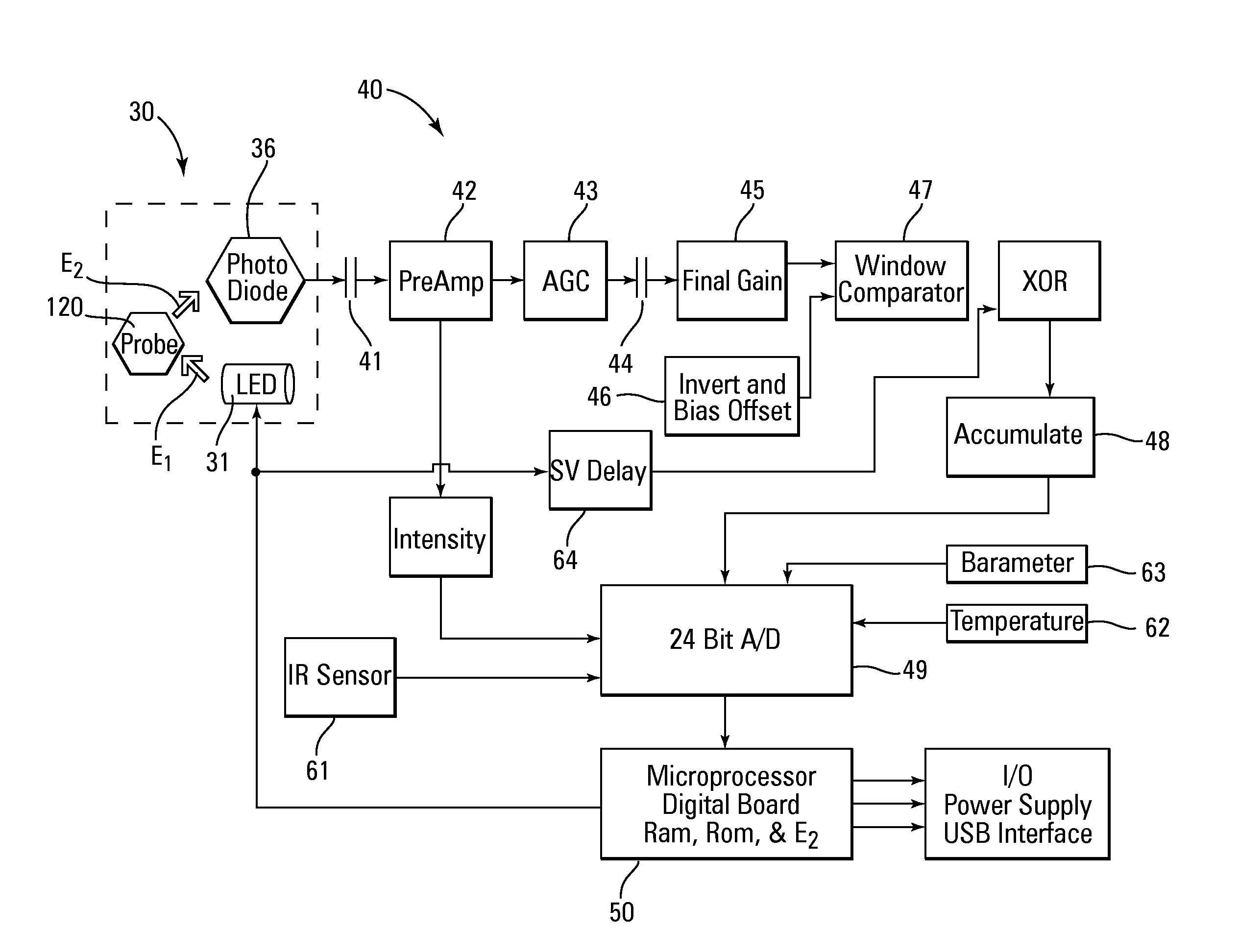
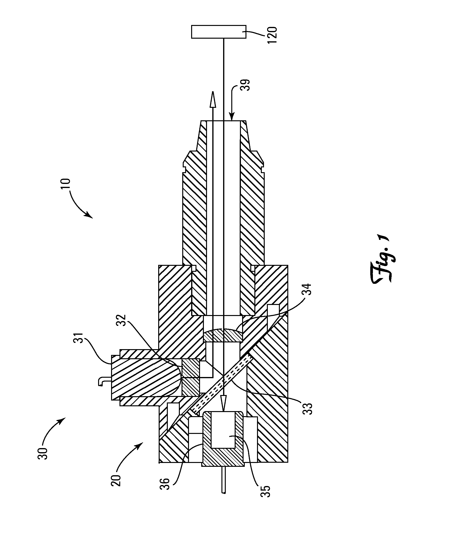
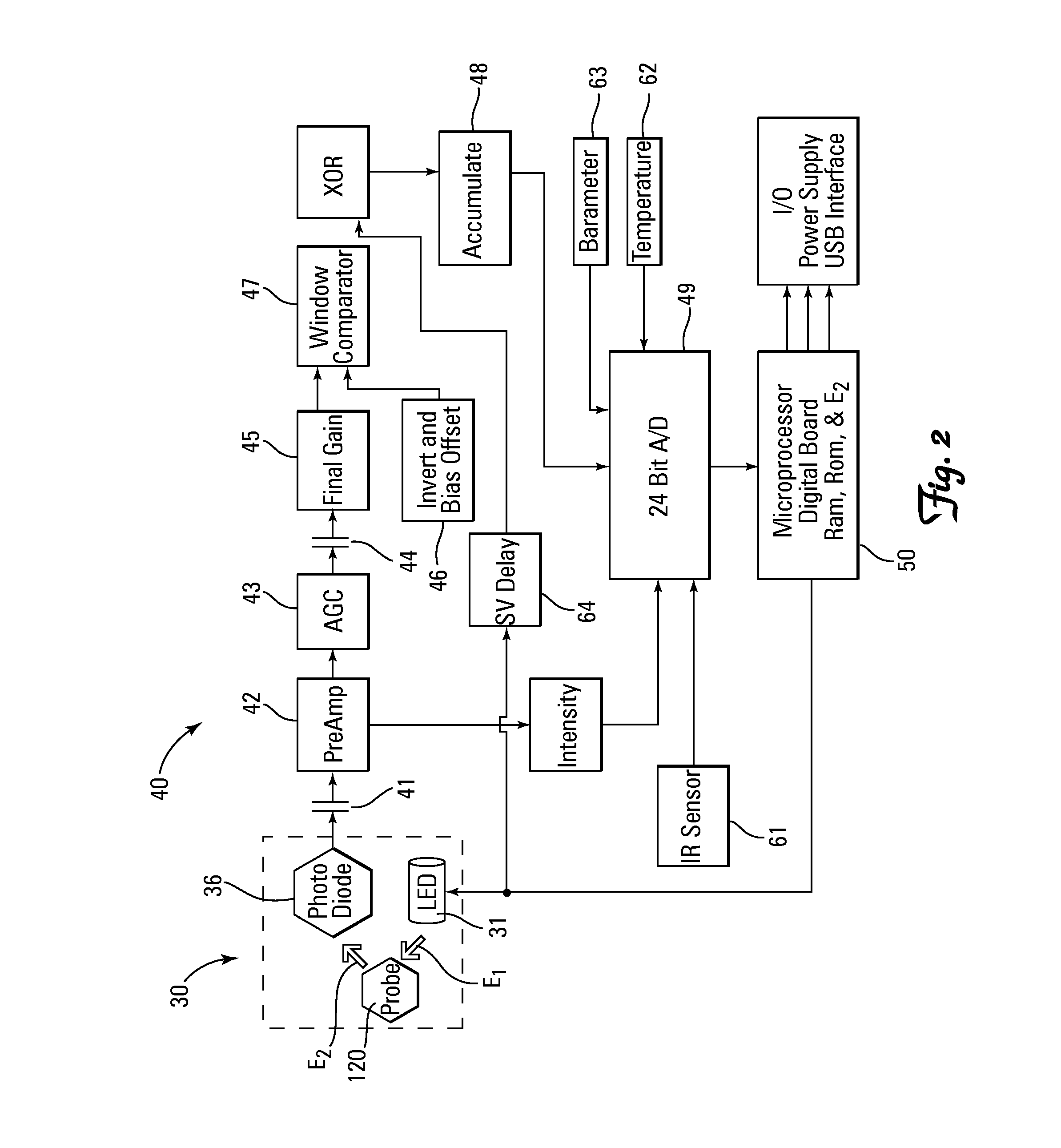
[0102]Luminescence lifetimes τ of a PtOEPK probe 120 exposed to known concentrations of O2 as set forth in Table One, were ascertained by measuring and accumulating approximately 300 τRise and τDecay employing the ΔtRise Delay, ΔtDecay Delay and the % Luminescence at tEnd as set forth in Table One. Three sets of accumulated values were averaged to obtain a raw measured τ time count set forth in Table One. The ΔtRise Delay and ΔtDecay Delay set forth in Table One are added together and subtracted from each raw measured τ time count to obtain a corrected τ time count as set forth in Table One. A Stern-Volmer Ratio was calculated at each O2 concentration by dividing the corrected τ time count obtained at an O2 concentration of 0 (τ0) by the corrected τ time count obtained at the given O2 concentration (τ) and subtracting 1 from the obtained quotient. A Stern-Volmer plot of O2 concentration v. Stern-Volmer Ratio is set forth in FIG. 3.

TABLE ONEτΔtRise Dela...


PUM

PropertyMeasurementUnit
decay delay timeaaaaaaaaaa

Abstract

A method of calibrating a luminescence lifetime sensing instrument 20 and of interrogating a target-analyte long-decay luminescence probe 120 includes measuring and reporting luminescence lifetime of the probe 120 employing excitation radiation filtered to remove emission radiation, or a starting time tstart delayed by a predetermined decay delay time, or delayed by a predetermined growth delay time, or an ending time comprising the time at which luminescence intensity has decayed or risen a predetermined percentage.

Description

[0001]This application claims the benefit of U.S. Provisional Application No. 61 / 317,509, filed Mar. 25, 2010BACKGROUND[0002]Solid-state polymeric materials based on target-analyte-sensitive photoluminescent dyes are widely used as optical target-analyte sensors and probes. See, for example United States Published Patent Applications 2009 / 0029402, 2008 / 8242870, 2008 / 215254, 2008 / 199360, 2008 / 190172, 2008 / 148817, 2008 / 146460, 2008 / 117418, 2008 / 0051646, and 2006 / 0002822, and U.S. Pat. Nos. 7,569,395, 7,534,615, 7,368,153, 7,138,270, 6,689,438, 5,718,842, 4,810,655, and 4,476,870. Such optical sensors are available from a number of suppliers, including Presens Precision Sensing, GmbH of Regensburg, Germany, Oxysense of Dallas, Tex., United States, and Luxcel Biosciences, Ltd of Cork, Ireland.[0003]Target-analyte partial pressure of a fluid system can be ascertained by placing a target-analyte quenchable luminescent probe into fluid communication with the system of interest (e.g., the e...

Claims


Application Information

Patent Timeline
Patent Type & Authority Applications(United States)
IPC IPC(8): G01N21/64G01D18/00
CPCG01N21/274Y10T436/209163G01N21/6408
Inventor MAYER, DANIEL W.HOWE, MICHAEL D.ASCHEMAN, TIMOTHY A.EASTMAN, JOHN
Owner MODERN CONTROLS
Learn More