Eureka AIR delivers breakthrough ideas for toughest innovation challenges, trusted by R&D personnel around the world.

CMOS compatible method for manufacturing a HEMT device and the HEMT device thereof

a technology of hemt devices and hemt devices, which is applied in the direction of semiconductor devices, semiconductor/solid-state device details, electrical apparatuses, etc., can solve the problems of schottky gates, current dispersion, and high gate leakag

Active Publication Date: 2012-12-20
INTERUNIVERSITAIR MICRO ELECTRONICS CENT (IMEC VZW)
View PDF8 Cites 66 Cited by
  • Summary
  • Abstract
  • Description
  • Claims
  • Application Information

AI Technical Summary

Benefits of technology

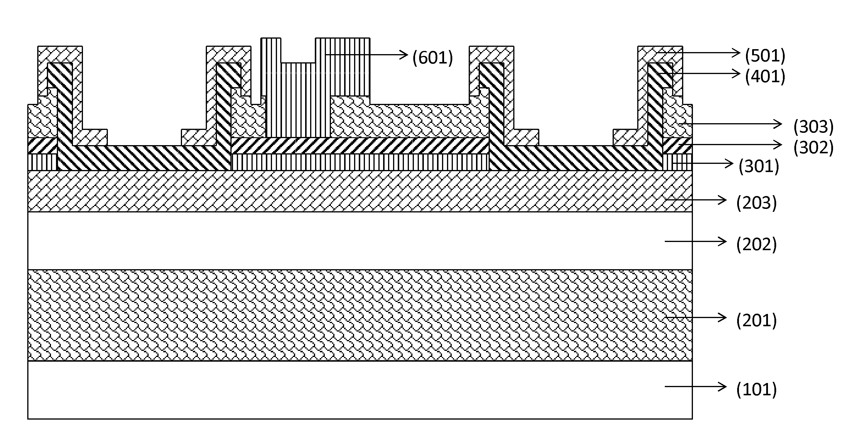
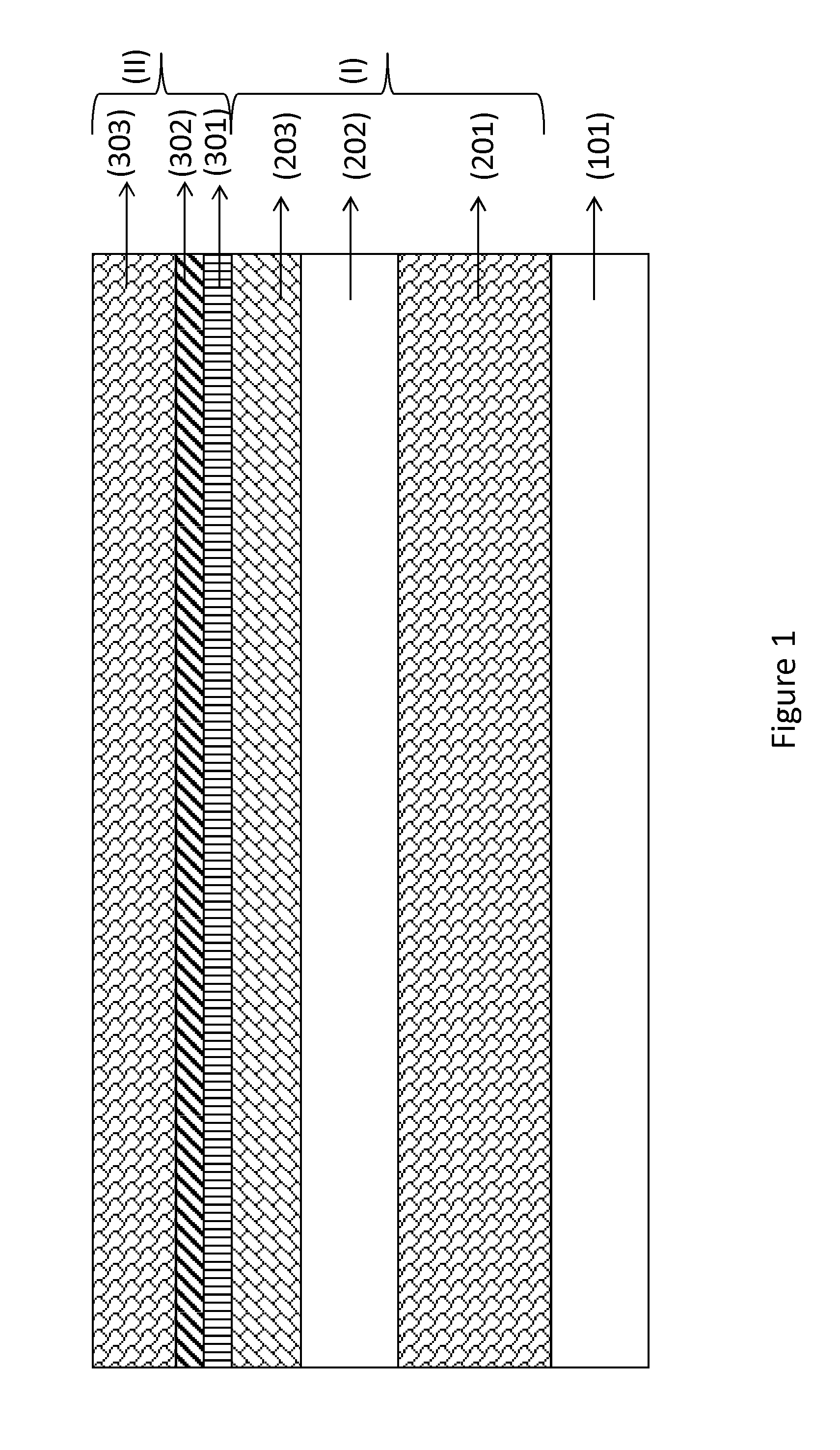
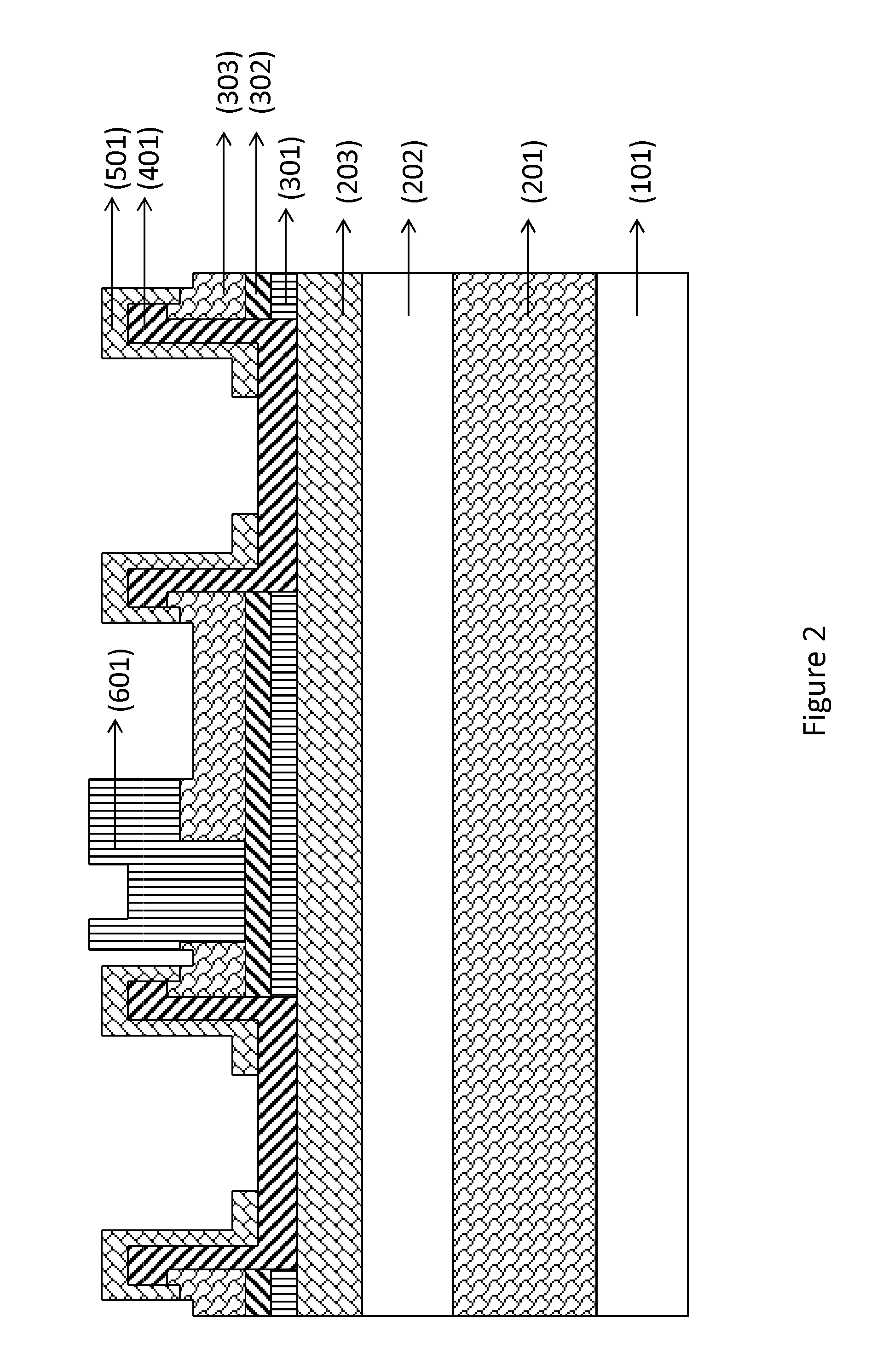
[0014]There is provided a method for manufacturing a III-nitride HEMT having a gate electrode and source and drain ohmic contacts, comprising a) providing a substrate; b) forming a stack of III-nitride layers on the substrate; c) forming a first passivation layer comprising silicon nitride, preferably Si3N4, overlying and in contact with an upper layer of the stack of III-nitride layers, wherein preferably the first passivation layer is deposited in-situ with the stack of III-nitride layers; d) forming a dielectric layer overlying and in contact with the first passivation layer; e) forming a second passivation layer comprising silicon nitride, prefer

Problems solved by technology

However, AlGaN / GaN HEMTs with Schottky gates and without passivation suffer from high gate leakage, current dispersion and a variety of reliability issues.
None of the methods referred above is suitable for use in a Si-CMOS compatible scheme.

Method used


Image

  • CMOS compatible method for manufacturing a HEMT device and the HEMT device thereof
  • CMOS compatible method for manufacturing a HEMT device and the HEMT device thereof
  • CMOS compatible method for manufacturing a HEMT device and the HEMT device thereof

Examples


Embodiment Construction

[0046]The present disclosure will be described with respect to particular embodiments and with reference to certain drawings but the disclosure is not limited thereto but only by the claims. The drawings described are only schematic and are non-limiting. In the drawings, the size of some of the elements may be exaggerated and not drawn on scale for illustrative purposes. The dimensions and the relative dimensions do not necessarily correspond to actual reductions to practice of the disclosure.

[0047]Furthermore, the terms first, second, third and the like in the description and in the claims, are used for distinguishing between similar elements and not necessarily for describing a sequential or chronological order. The terms are interchangeable under appropriate circumstances and the embodiments of the disclosure can operate in other sequences than described or illustrated herein.

[0048]Moreover, the terms top, bottom, over, under and the like in the description and the claims are use...


PUM


Abstract

A method for manufacturing a III-nitride HEMT having a gate electrode and source and drain ohmic contacts is provided, comprising providing a substrate; forming a stack of III-nitride layers on the substrate; forming a first passivation layer comprising silicon nitride overlying and in contact with an upper layer of the stack of III-nitride layers, wherein the first passivation layer is deposited in-situ with the stack of III-nitride layers; forming a dielectric layer overlying and in contact with the first passivation layer; forming a second passivation layer comprising silicon nitride overlying and in contact with the dielectric layer wherein the second passivation layer is deposited at a temperature higher than 450° C. by LPCVD or MOCVD or any equivalent technique; and thereafter forming the source and drain ohmic contacts and the gate electrode.

Description

CROSS-REFERENCE TO RELATED APPLICATIONS[0001]This application claims the benefit under 35 U.S.C. §119(e) of U.S. provisional application Ser. No. 61 / 498,951 filed Jun. 20, 2011 and U.S. provisional application Ser. No. 61 / 526,107 filed Aug. 22, 2011, the disclosures of which are hereby expressly incorporated by reference in their entirety and are hereby expressly made a portion of this application.FIELD OF THE DISCLOSURE[0002]Semiconductor devices are provided. More particularly, a method for manufacturing a high electron mobility transistor (HEMT) device and the HEMT device thereof are provided.BACKGROUND OF THE DISCLOSURE[0003]Gallium-nitride based high electron mobility transistors (HEMTs) have attracted a lot of interest for high-frequency and lately also high-power applications because of their potentials for fast and low-loss switching, high breakdown voltage and high operating temperature.[0004]However, AlGaN / GaN HEMTs with Schottky gates and without passivation suffer from h...

Claims


Application Information

Patent Timeline
IPC IPC(8): H01L29/778H01L21/20
CPCH01L23/291H01L29/2003H01L29/513H01L29/66462H01L29/7783H01L29/7786H01L29/7787H01L29/518H01L2924/0002H01L2924/00H01L23/3171H01L29/205
Inventor VAN HOVE, MARLEEN
Owner INTERUNIVERSITAIR MICRO ELECTRONICS CENT (IMEC VZW)
Why Eureka
Eureka Blog
Learn More