
Storage device, control method for same and system management program

a technology of storage devices and control methods, applied in the direction of climate sustainability, memory adressing/allocation/relocation, instruments, etc., can solve the problems of reducing the power consumption and management cost of the storage device, affecting the performance of the response time and throughput, and increasing the power consumption of the storage device. , to achieve the effect of saving power consumption and saving power consumption

Inactive Publication Date: 2012-12-13
TOKYO INST OF TECH
View PDF11 Cites 16 Cited by
  • Summary
  • Abstract
  • Description
  • Claims
  • Application Information

AI Technical Summary

Benefits of technology

[0026]With the procedure as described above, the control method for a storage device in accordance with the sixth aspect of the present invention can have advantageous effects similar to those of the control method for a storage device in accordance with the fifth aspect of the present invention. Further, in the control method described above, the step of storing a copy of a data of interest in the cache disk, during the time during which the data disk is in the normal rotation state. This can prevent unnecessarily rotation operations of the data disk. Thus, the read processing can be stably performed by the cache disk, and the data disk can be kept in the normal rotation stop state for a longer period of time.
[0028]With the procedure as described above, in the control method for a storage device in accordance with the seventh aspect of the present invention, when a read request is made, a candidate storage place in which a data for which the read request is made is stored is sequentially searched by the system management unit. That is, the primary data area in the cache memory is the top priority to be searched as the candidate storage place by the system management unit. After that, the backup data area in the cache memory as a backup thereof is searched. Only when the target read data has not been read in the above-described steps, the system management unit accesses the data disk. The data disk can be kept in the normal rotation stop state until those steps are completed. Also, when the system management unit accesses the data disk, if at least either one of the primary side or the backup side of the data disk is in the normal rotation stop state, the data disk on a side to which the access is not made can be still kept in the normal rotation stop state. That is, in the control method for the storage device, such control is provided that the data disk both on the primary side and the backup side is kept in the normal rotation stop state as long as possible. And, only when it is absolutely necessary, the data disk on the primary side or on the backup side is spun up to rotate in the normal rotation state. This can realize a drastic saving of power consumption.
[0030]With the procedure as described above, the control method for a storage device in accordance with the eighth aspect of the present invention can have advantageous effects similar to those of the control method for a storage device in accordance with the seventh aspect of the present invention. Further, when a read request is made and a candidate storage place in which a data for which the read request is made is stored is sequentially searched, the cache disk is preferentially searched, rather than the data disk cache disk. A hit in the cache disk allows the data disk to be kept in the normal rotation stop state for a longer time period.

Problems solved by technology

On the other hand, power consumption of the storage device has also been increased.
Reduction in the power consumption and management cost of the storage device has now been regarded as a pressing problem with respect to a measure against global warming.
It is concerned, however, that the stop of rotation of a magnetic disk device could degrade its performance in regard to a response time and a throughput.

Method used


Image

  • Storage device, control method for same and system management program
  • Storage device, control method for same and system management program
  • Storage device, control method for same and system management program

Examples


example

[0271]In order to demonstrate advantageous effects of the present invention, computer simulation for verifying performance of the storage device of the present invention was carried out.

(Experimental Method)

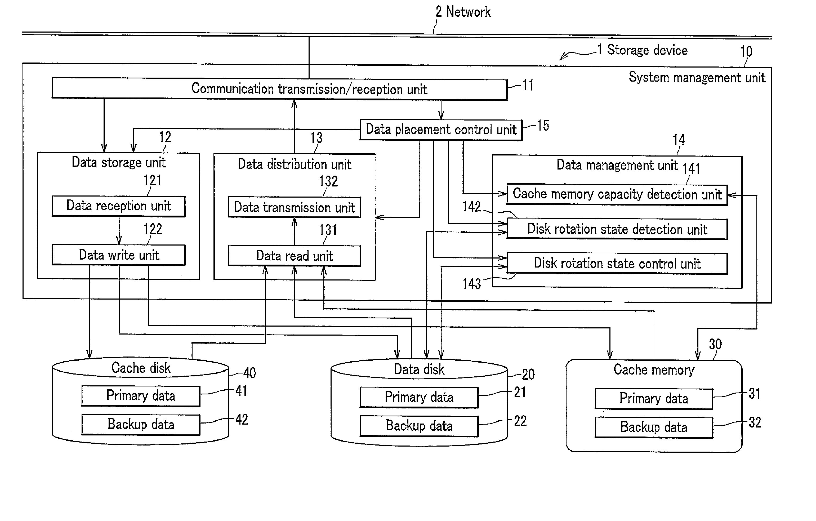
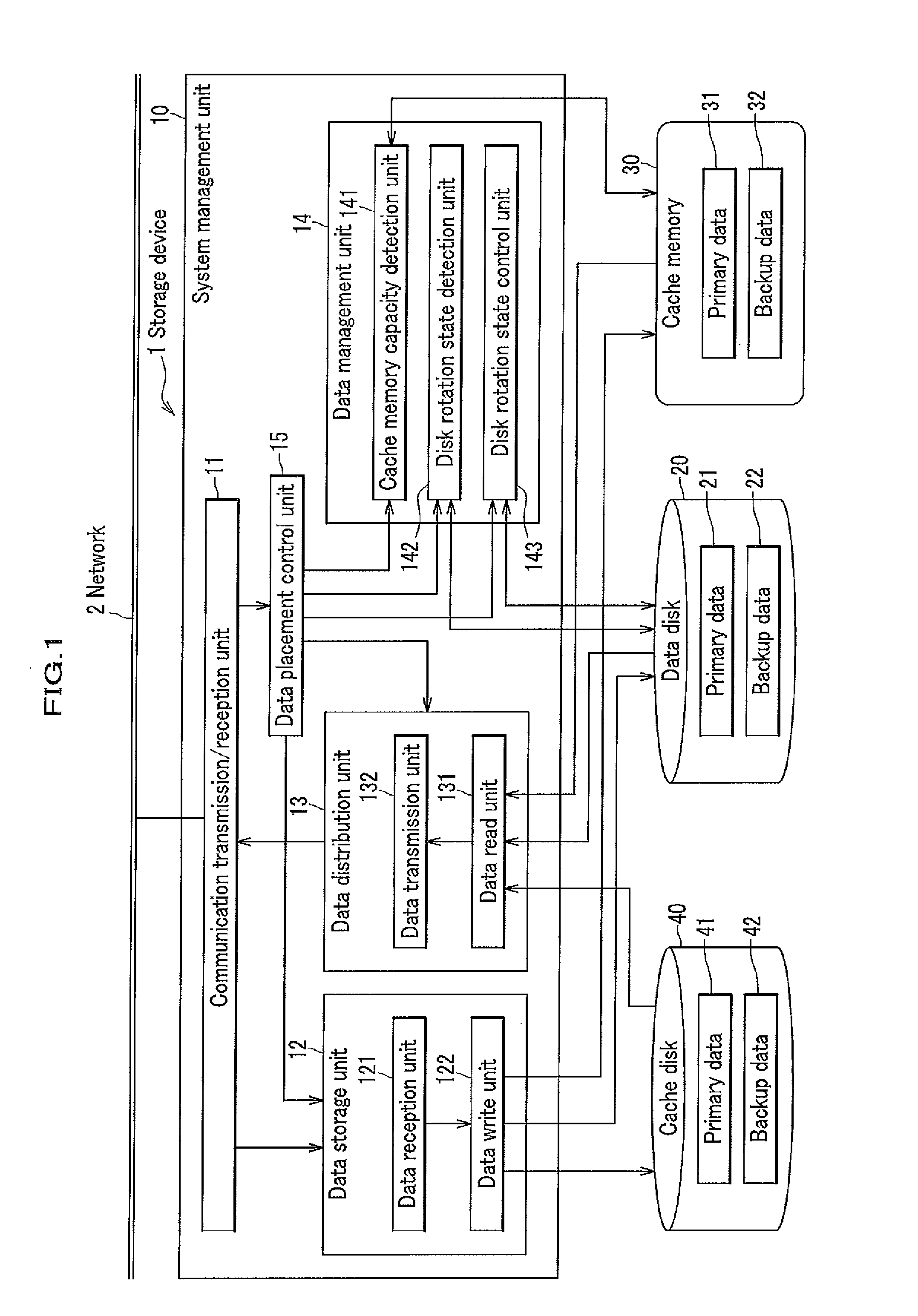
[0272]In this Example, a storage device of the present invention was configured to include the system management unit, the data disk 20, the cache memory 30, and the cache disk 40 and provide control of stopping as many data disks 20 as possible by the control method described above. An experiment was conducted for estimating an effect of reducing power consumption of the storage device of the present invention, compared to a conventional storage device. The conventional storage device used herein had a configuration in which the cache memory 30 and the cache disk 40 were not included, all of the data disk 20 were constantly in the rotation state, and a specific control as that of the Example was not provided. Table 1 lists explanations of symbols used in expressions below.

TABLE ...


PUM


Abstract

A storage device has plural data disks including a primary data area and a backup data area. Performance and reliability are secured while conserving power. A system management means includes a disk rotational state detection means, a disk rotational state control means for rotating or stopping a data disk, and a data placement control means for accessing the data disk to move the data. The data placement control means, if the data disk of the primary or backup side has been stopped at writing time, spins up and accesses thereof, and if the data disk of the primary or backup side has been stopped at reading time, prioritizes the side that is being rotated and accesses thereto, and if the data disk of the primary and backup side have both been stopped at reading time, spins up and accesses the side that has been stopped for the longer time.

Description

TECHNICAL FIELD[0001]The present invention is related to: a storage device which includes a plurality of data disks each having a primary data area and a backup data area and stores apiece of data both in a primary data area in one of the data disks and in a backup data area in another data disk thereof; and control of the storage device.BACKGROUND ART[0002]A conventional technique has been known in which a data is made redundant and can be quickly recovered in case of failure by storing an original data and a backup data of the original data in a distributed manner in a plurality of data disks of a storage device (see, for example, Patent Document 1). In such a storage device, a data disk has plural logical storage sections which include a primary area in which an original data is stored and a backup area in which a backup data of the original data is stored. The storage device is equipped with a plurality of data disks each having a primary data area and a backup data area. The st...

Claims


Application Information

Patent Timeline
Patent Type & Authority Applications(United States)
IPC IPC(8): G06F12/08
CPCG06F3/0634G06F3/068G06F11/2071G06F3/0625Y02D10/00
Inventor YOKOTA, HARUOHIKIDA, SATOSHI
Owner TOKYO INST OF TECH
Learn More