Liquid Crystal Display Device

a liquid crystal display and display device technology, applied in non-linear optics, instruments, optics, etc., can solve problems such as degrading image quality, and achieve the effects of preventing generation of failure in the market, preventing generation of alignment film scraping, and improving production yield of liquid crystal display devices

Active Publication Date: 2012-12-13
JAPAN DISPLAY INC
View PDF1 Cites 18 Cited by
  • Summary
  • Abstract
  • Description
  • Claims
  • Application Information

AI Technical Summary

Benefits of technology

[0013]The present invention intends to suppress the generation of the light spots by providing a countermeasure for the scraped off shavings of the alignment film caused by the columnar spacer.
[0024]According to the invention, in the liquid crystal display device having the columnar spacer and using the optical alignment film, since scraping of the alignment film caused by the columnar spacer can be prevented, production yield of the liquid crystal display device can be improved. Further, since scraping of the alignment film, which is caused by the lateral displacement of the columnar spacer attributable to the temperature cycles after shipping or the pressure from the outside to the counter substrate, can be prevented, generation of failure in the market can be prevented.
[0025]In a liquid crystal display device of a liquid crystal injection type using a dropping method, the number of columnar spacers is small and a stress between the columnar spacer and the pedestal per one set is large. According to the invention, since the alignment film is not present or the film thickness is smaller than that in other portions in the pedestal in contact with the columnar spacer, generation of the scraping of alignment film can be prevented. Thus, generation of light spots can be prevented.

Problems solved by technology

When scraped off shavings of the alignment film intrude into the liquid crystal layer, light spots are generated to degrade the image quality.

Method used


Image

  • Liquid Crystal Display Device
  • Liquid Crystal Display Device
  • Liquid Crystal Display Device

Examples


embodiment 1

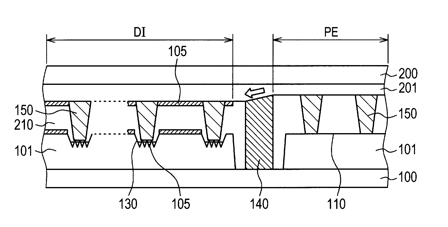
[0043]FIG. 1 is a cross sectional view of a liquid crystal display device according to the invention. The basic configuration of FIG. 1 is identical with that in FIG. 2. That is, a concave pedestal is formed on the organic passivation film 101 in the pixel region so that the TFT substrate 100 and the counter substrate 200 are convexed inward as shown in FIG. 3 to make the gap between the TFT substrate 100 and the counter substrate 200 smaller in the pixel portion than in the periphery.

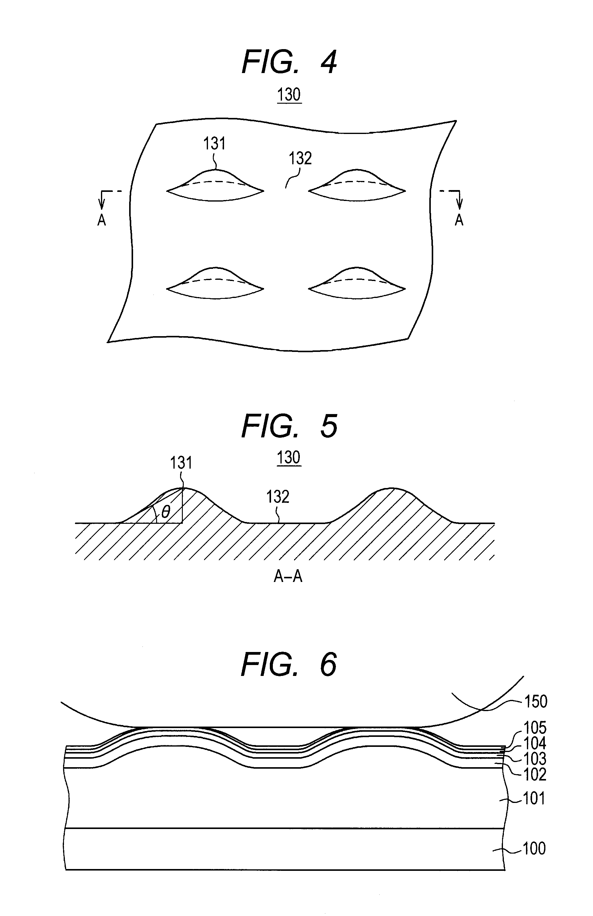
[0044]FIG. 1 is different from FIG. 2 in that a concavo-convex portion is formed at the bottom of the concave pedestal for preventing scraping of the alignment film by the columnar spacer 150. The pedestal in FIG. 1 is hereinafter referred to as a concavo-convex pedestal 130. That is, in the concavo-convex pedestal 130, the concavo-convex portion is formed at the bottom of the concave pedestal 120 formed on the organic passivation film 101.

[0045]In FIG. 1, while a convex portion 131 and a concave porti...

embodiment 2

[0064]FIG. 8 is a perspective view showing the shape of the bottom of the concavo-convex pedestal 130 according to a second embodiment of the invention. In FIG. 8, a concavo-convex portion at the bottom of the concavo-convex pedestal 130 is formed only in one direction (x direction).

[0065]That is, in FIG. 8, concavo-convex portions are formed continuously at a predetermined pitch P in the lateral direction (x direction) and ridges of the convex portions 131 are formed in the vertical direction (y direction). Also in the shape of FIG. 8, the alignment film 105 is not present on the convex portion 131, and the alignment film 105 is formed at a large thickness in the concave portion 132.

[0066]In FIG. 8, while the columnar spacer 150 is in contact with the convex portions 131, since the alignment film 105 is not present on the convex portions 131, the alignment film 105 is not scraped off even when the columnar spacer 150 should displace laterally. For preventing the columnar spacer 150...


PUM

PropertyMeasurementUnit
angleaaaaaaaaaa
angleaaaaaaaaaa
angleaaaaaaaaaa

Abstract

A liquid crystal display device includes a TFT substrate having an organic passivation film, and a counter substrate, with liquid crystals inside of the liquid crystal display device. A columnar spacer is formed on the counter substrate, which defines a distance between the TFT substrate and the counter substrate, and a concavo-convex pedestal is formed in a pixel region of the TFT substrate, the concavo-convex pedestal being provided in facing relation to the columnar spacer. The concavo-convex pedestal is formed with a convex portion and a concave portion at a bottom of the concavo-convex pedestal, with a top end of the columnar spacer being in contact with two or more convex portions formed on the bottom of the concavo-convex pedestal, and an area at the bottom of the concavo-convex pedestal being larger than the area at the top end of the columnar spacer.

Description

CLAIM OF PRIORITY[0001]The present application claims priority from Japanese Patent Application JP 2011-128815 filed on Jun. 9, 2011, the content of which is hereby incorporated by reference into this application.BACKGROUND OF THE INVENTION[0002]1. Field of the Invention[0003]The present invention relates to a liquid crystal display device. The invention more particularly relates to a liquid crystal display device configured to take a countermeasure against light spots attributable to shavings of an alignment film.[0004]2. Description of the Related Art[0005]Liquid crystal display devices include a TFT substrate having pixel electrodes, thin film transistors (TFT), etc. formed in a matrix; a counter substrate disposed in facing relation to the TFT substrate and having color filters, etc. formed at positions corresponding to the pixel electrodes of the TFT substrate; and liquid crystals put between the TFT substrate and the counter substrate. Images are formed by controlling the ligh...

Claims


Application Information

Patent Timeline
Patent Type & Authority Applications(United States)
IPC IPC(8): G02F1/1339
CPCG02F1/133371G02F1/13378G02F1/13394G02F2001/13415G02F2001/13398G02F1/1339G02F1/1341G02F1/1368G02F2201/50G02F1/13415G02F1/13398
Inventor HYODO, YOSUKEIGETA, KOICHIKANEKO, TOSHIKIKUNIMATSU, NOBORUSONODA, HIDEHIRO
Owner JAPAN DISPLAY INC
Why Eureka
Try Eureka