
Bone grafts

a technology of bone grafts and grafts, applied in the field of spacers, compositions, instruments and methods for arthrodesis, can solve the problems of affecting the function of the bone graft, so as to promote bone ingrowth, avoid stress shielding, and encourage bone ingrowth

Inactive Publication Date: 2012-12-06
PAFFORD JOHN +4
View PDF3 Cites 8 Cited by
  • Summary
  • Abstract
  • Description
  • Claims
  • Application Information

AI Technical Summary

Benefits of technology

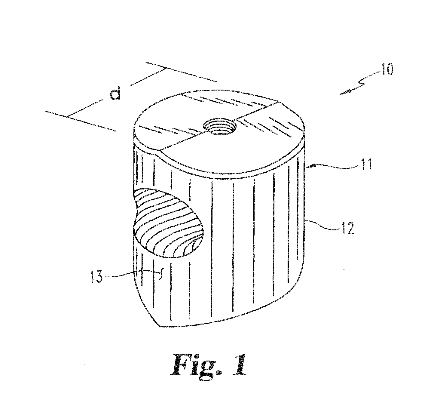
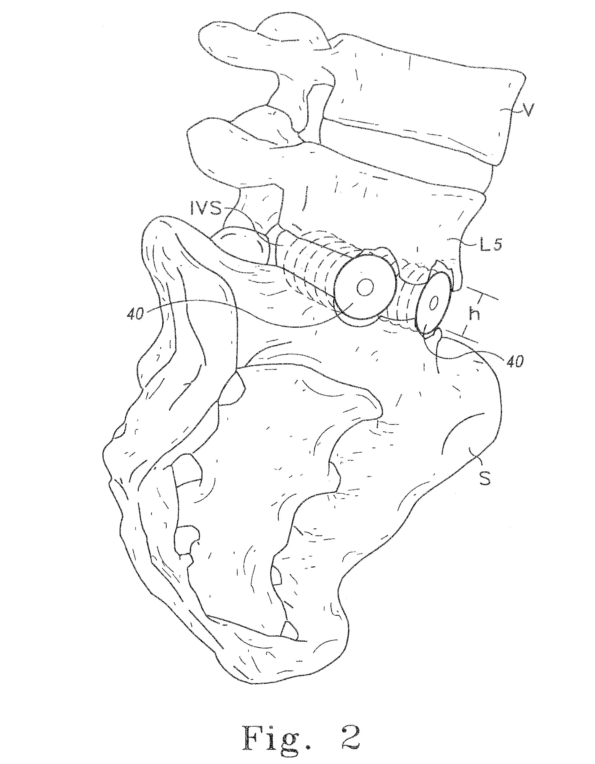
[0020]One object of the invention is to provide spacers for engagement between vertebrae which encourages bone ingrowth and avoids stress shielding. Another object of the invention is to provide a spacer which restores the intervertebral disc space and supports the vertebral column while promoting bone ingrowth.

Problems solved by technology

Spinal discs may be displaced or damaged due to trauma, disease or aging.
The extruded nucleus pulposus may press on the spinal nerve, which may result in nerve damage, pain, numbness, muscle weakness and paralysis.
Intervertebral discs may also deteriorate due to the normal aging process or disease.
As a disc dehydrates and hardens, the disc space height will be reduced leading to instability of the spine, decreased mobility and pain.
Collapse of the disc space can cause instability of the spine, abnormal joint mechanics, premature development of arthritis or nerve damage, in addition to severe pain.
Moreover, the surgical procedures necessary to implant a rod or plate to stabilize the level during fusion were frequently lengthy and involved.
Success of the discectomy and fusion procedure requires the development of a contiguous growth of bone to create a solid mass because the implant may not withstand the cyclic compressive spinal loads for the life of the patient.
Unfortunately, due to the stiffness of the material, some metal implants may stress shield the bone graft, increasing the time required for fusion or causing the bone graft to resorb inside the cage.
Subsidence, or sinking of the device into bone, may also occur when metal implants are implanted between vertebrae if fusion is delayed.
Metal devices are also foreign bodies which can never be fully incorporated into the fusion mass.
Such dowels have relatively poor biomechanical properties, in particular a low compressive strength.
Therefore, the Cloward dowel is not suitable as an intervertebral spacer without internal fixation due to the risk of collapsing prior to fusion under the intense cyclic loads of the spine.
Unfortunately, the use of bone grafts presents several disadvantages.
The additional surgery also increases the risk of infection and blood loss and may reduce structural integrity at the donor site.
Furthermore, some patients complain that the graft harvesting surgery causes more short-term and long-term pain than the fusion surgery.
However, allogenic bone does not have the osteoinductive potential of autogenous bone and therefore may provide only temporary support.
The slow rate of fusion using allografted bone can lead to collapse of the disc space before fusion is accomplished.
Both allograft and autograft present additional difficulties.
Graft alone may not provide the stability required to withstand spinal loads.
Internal fixation can address this problem but presents its own disadvantages such as the need for more complex surgery as well as the disadvantages of metal fixation devices.
This trial and error approach increases the length of time required for surgery.
Furthermore, the graft material usually has a smooth surface which does not provide a good friction fit between the adjacent vertebrae.
Slippage of the graft may case neural and vascular injury, as well as collapse of the disc space.
Even where slippage does not occur, micromotion at the graft / fusion-site interface may disrupt the healing process that is required for fusion.
In each case developing an implant having the biomechanical properties of metal and the biological properties of bone without the disadvantages of either has been extremely difficult or impossible.

Method used


Image

  • Bone grafts
  • Bone grafts
  • Bone grafts

Examples


example 1

Diaphysial Cortical Bone Dowel

[0125]A consenting donor (i.e., donor card or other form of acceptance to serve as a donor) was screened for a wide variety of communicable diseases and pathogens, including human immunodeficiency virus, cytomegalovirus, hepatitis B, hepatitis C and several other pathogens. These tests may be conducted by any of a number of means conventional in the art, including but not limited to ELISA assays, PCR assays, or hemagglutination. Such testing follows the requirements of: (i) American Association of Tissue Banks, Technical Manual for Tissue Banking, Technical Manual—Musculoskeletal Tissues, pages M19-M20; (ii) The Food and Drug Administration, Interim Rule, Federal Register / Vol. 50, No. 238 / Tuesday, Dec. 14, 1993 / Rules and Regulations / 65517, D. Infectious Disease Testing and Donor Screening, (iii) MMWR / Vol. 43 / No. RR-8, Guidelines for Preventing Transmission of Human Immunodeficiency Virus Through Transplantation of Human Tissue and Organs, pages 4-7; (iv...

example 2

Threaded Dowels

[0130]A diaphysial cortical bone dowel is prepared as described above. The plug is then machined, preferably in a class 10 clean room, to the dimensions desired. The machining is preferably conducted on a lathe such as a jeweler's lathe or machining tools may be specifically designed and adapted for this purpose. A hole is then drilled through the anterior wall of the dowel. The hole is then tapped to receive a threaded insertion tool.

example 3

Bone Dowel Soaked with rhBMP-2

[0131]A threaded dowel is obtained through the methods of Examples 1 and 2. A vial containing 4.0 mg of lyophilized rhBMP-2 (Genetics Institute) is constituted with 1 mL sterile water (Abbott Laboratories) for injection to obtain a 4.0 mg / mL solution as follows:[0132]1. Using a 3-cc syringe and 22 G needle, slowly inject 1.0 mL sterile water for injection into the vial containing lyophilized rhBMP-2.[0133]2. Gently swirl the vial until a clear solution is obtained. Do not shake.

[0134]The dilution scheme below is followed to obtain the appropriate rhBMP-2 concentration. This dilution provides sufficient volume for two dowels. The dilutions are performed as follows:[0135]1. Using a 5-cc syringe, transfer 4.0 mL of MFR 906 buffer (Genetics Institute) into a sterile vial.[0136]2. Using a 1-cc syringe, transfer 0.70 mL reconstituted rhBMP-2 into the vial containing the buffer.[0137]3. Gently swirl to mix.

DILUTION SCHEMEINITIAL rhBMP-2rhBMP-2MFR-842FINAL rhBM...


PUM

PropertyMeasurementUnit
widthaaaaaaaaaa
widthaaaaaaaaaa
angleaaaaaaaaaa

Abstract

Spinal spacers 20 are provided for fusion of a motion segment. The spacers include a load bearing member 21 having a wall 22 sized for engagement within a space between adjacent vertebrae to maintain the space and an effective amount of an osteogenic composition to stimulate osteoinduction. The osteogenic composition includes a substantially pure osteogenic factor in a pharmaceutically acceptable carrier. In one embodiment the load bearing member includes a hone graft impregnated in an osteogenic composition. In another embodiment, the osteogenic composition 30 is packed within a chamber 25 defined in the graft. Any suitable configuration of a bone graft is contemplated, including bone dowels, D-shaped spacers and cortical rings.

Description

CROSS REFERENCE TO RELATED APPLICATIONS[0001]This application is a continuation of co-pending U.S. patent application Ser. No. 10 / 781,058 filed Feb. 18, 2004, which is a continuation of U.S. patent application Ser. No. 10 / 114,675 filed Apr. 2, 2002 and now abandoned, which is a continuation of U.S. patent application Ser. No. 09 / 484,354 filed Jan. 18, 2000 and issued as U.S. Pat. No. 6,371,988, which is a divisional of U.S. patent application Ser. No. 08 / 740,031 filed Oct. 23, 1996 and now abandoned, which is a continuation-in-part of U.S. patent application Ser. No. 08 / 603,676 filed Feb. 20, 1996 and issued as U.S. Pat. No. 6,423,095, which is a continuation-in-part of U.S. patent application Ser. No. 08 / 543,563 filed Oct. 16, 1995 and now abandoned, the entire contents of each application hereby being incorporated by reference in its entirety.FIELD OF THE INVENTION[0002]The present invention relates to spacers, compositions, instruments and methods for arthrodesis. In specific app...

Claims


Application Information

Patent Timeline
Patent Type & Authority Applications(United States)
IPC IPC(8): A61F2/44
CPCA61L27/54A61L2430/38A61F2/30767A61F2/442A61F2/4455A61F2/446A61F2/447A61F2/4611A61F2/468A61B2017/0256A61B2019/304A61F2002/2817A61F2002/2835A61F2002/2839A61F2002/30004A61F2002/30057A61F2002/30062A61F2002/30075A61F2002/30112A61F2002/30136A61F2002/30153A61F2002/30187A61F2002/30224A61F2002/30235A61F2002/30261A61F2002/30271A61F2002/30677A61F2002/30772A61F2002/30774A61F2002/30787A61F2002/30797A61F2002/30813A61F2002/30836A61F2002/30841A61F2002/30848A61F2002/3085A61F2002/30866A61F2002/30879A61F2002/30892A61F2002/30904A61F2002/3092A61F2002/30929A61F2002/4475A61F2002/448A61F2002/4623A61F2002/4627A61F2002/4628A61F2002/4649A61F2310/00161A61F2310/00293A61F2310/00365A61F2310/00491A61F2310/00544A61F2310/00796A61L27/3608A61L2300/414A61F2/30724A61B2090/034A61F2/4603A61F2002/30593A61F2002/30845
Inventor PAFFORD, JOHNBOYD, LAWRENCE M.MCKAY, WILLIAM F.RAY, III, EDDIE F.VAN HOECK, JAMES E.
Owner PAFFORD JOHN
Learn More