
Home wiring test system with missing filter detection

a technology for home wiring and filter detection, applied in the direction of substation equipment, electrical equipment, surveillance/monitoring/testing arrangements, etc., can solve the problems of customer cost, customer cost, and service provider cost, and achieve the effect of cost saving or frustrating the customer, and reducing the cost of dispatching a technician

Active Publication Date: 2012-12-06
TOLLGRADE COMM INC
View PDF6 Cites 22 Cited by
  • Summary
  • Abstract
  • Description
  • Claims
  • Application Information

AI Technical Summary

Benefits of technology

[0007]Some embodiments relate to a method to detect a service affecting condition in a communications network associated with a missing filter. The method includes, with a test device connected to a conductor of the communications network, measuring a spectrum on the conductor to determine first spectrum information. The method also includes detecting a communication device connected to the communication network in an in-use state. The method additionally includes, while the communication device is in the in-use state, with the test device, measuring a spectrum on the conductor to determine second spectrum information. The method further includes indicating a missing filter when the second spectrum information deviates from the first spectrum information by more than a threshold amount.

Problems solved by technology

Communication services can be degraded or interrupted due to faults in either the network or the wiring local to the customer's premises.
Nonetheless, when problems occur with the customer's service, the customer may call the service provider for assistance, whether or not the problem is caused by a fault in the customer premises wiring or the service provider's network.
Dispatching a technician can be costly for the service provider.
In some instances, the service provider will impose a charge on the customer for dispatching a technician to the customer's premises, which can also be costly or frustrating for the customer.
Even if a technician is not dispatched, the cost of maintaining a customer support center with personnel and test systems to respond to customer calls can be costly for the service provider.
Furthermore, the inventors have recognized and appreciated that existing techniques for testing wiring by a service provider may be insufficient for detecting wiring faults at a customer's location.
In particular, noise or interference problems that occur at high frequencies may be difficult to detect from a remote location.

Method used


Image

  • Home wiring test system with missing filter detection
  • Home wiring test system with missing filter detection
  • Home wiring test system with missing filter detection

Examples


example 1

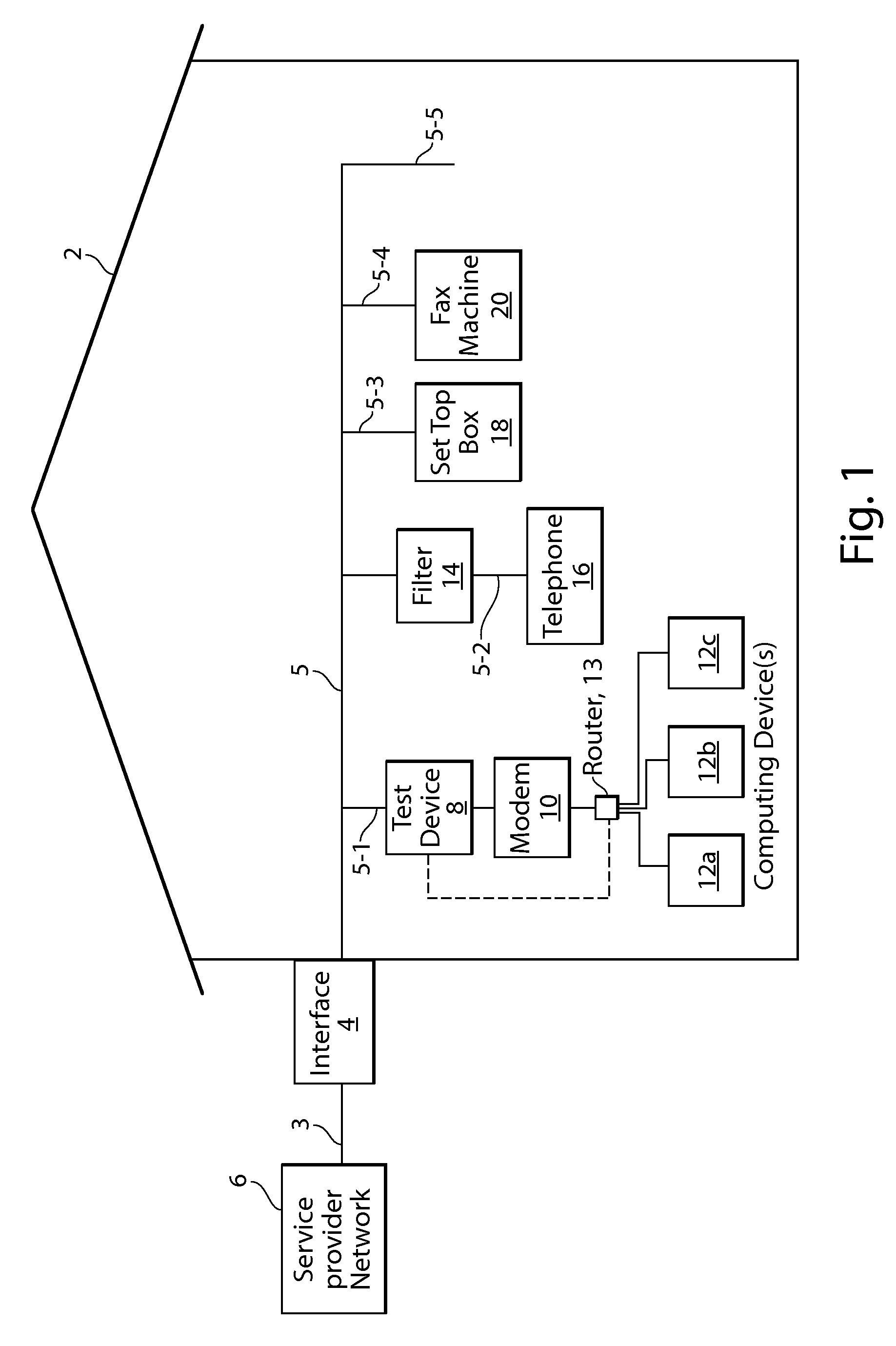
[0144]FIG. 7a shows the structure of a test device 8a, which is an example of test device 8 that may be used in some embodiments, such as the embodiment shown in FIG. 1. As illustrated in FIG. 7a, test device 8a may include a housing 32, which may be an RF shielded housing. A cable 34 including an RJ 11 plug 36 may be used for connecting port 22 of test device 8 to an RJ11 socket or DSL port of modem 10. Test device 8a may include an RJ 11 socket 38 for connection of port 24 to an RJ 11 plug of unfiltered extension 5-1. The communication interface 29 of test device 8a may also include a port 44 for connecting the test device 8a to a computing device 12. In some embodiments, port 44 may be a USB port (e.g., a mini USB-B port). The user interface 28 of test device 4a may include a button 42 for activation by a user, one or more status LEDs 46 (such as a red LED 46-1 and green LED 46-2), and a display 48, such as, without limitation, a 7-segment LED display.

[0145]As shown in FIG. 7b, h...

example 2

[0213]Another embodiment will be described with respect to FIG. 8. As shown in FIG. 8, an in-home or residential communication network 802 receives broadband service from a broadband service provider 804 via a communication line 806. Communication line 806 can include suitable types of conductors, such as a wire pair, a twisted pair, a coaxial cable, or a fiber optic line for providing, without limitation, DSL service to communication network 802. Any suitable type of data service may be provided by broadband service provider 804 to communication network 802 via communication line 806.

[0214]Communication network 802 includes a residential gateway 808 which includes a wide area network (WAN) port 810 for receiving broadband services from broadband service provider 804 via communication line 806 and a local area network (LAN) port 812 for providing high speed data service (e.g., Ethernet service) to other nodes of communication network 802. As is known in the art, residential gateway ...


PUM


Abstract

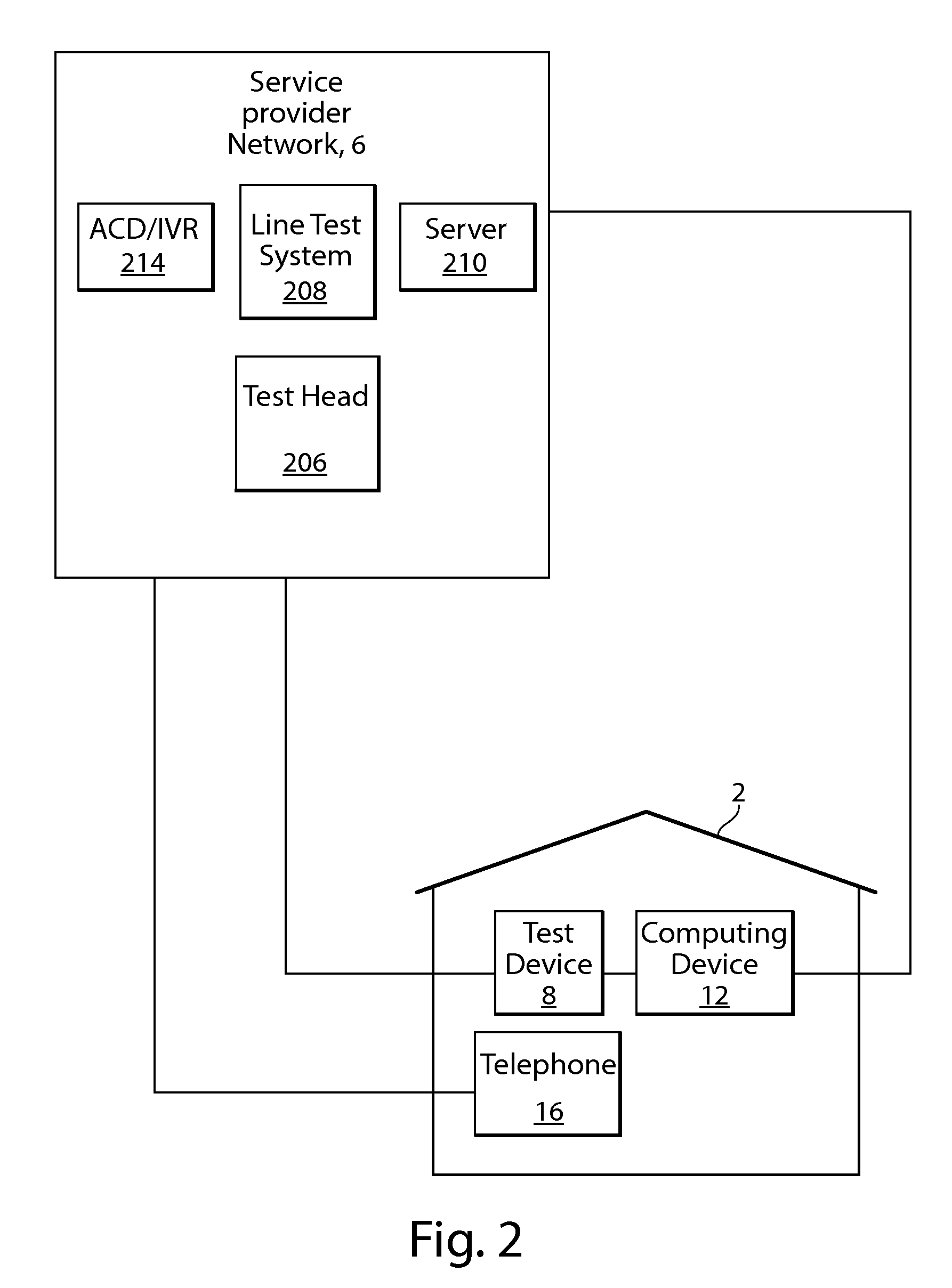
A system for testing a conductor of a structure can include a test device connected to the conductor. The test device is configured to test an electrical characteristic of the conductor and to produce a test result based at least in part on the electrical characteristic. A service provider network may be configured to communicate with the test device to initiate a test and / or to obtain the test result. A customer may use a computing device to obtain information regarding the test result, as well as guidance for troubleshooting and resolving a problem detected with the electrical conductor, such as a fault.

Description

RELATED APPLICATIONS[0001]This application is a continuation-in-part of and claims priority under 35 U.S.C. 120 to U.S. patent application Ser. No. 13 / 279,382, filed on Oct. 24, 2011, titled “Communications Wiring Noise Level Monitor and Alarm Indicator,” which claims the benefit under 35 U.S.C. 119(e) of U.S. Provisional Application 61 / 405,846, filed on Oct. 22, 2010 titled “In Home Communications Wiring Noise Level Monitor and Alarm Indicator;” and is a continuation-in-part of and claims priority under 35 U.S.C. 120 to U.S. patent application Ser. No. 13 / 279,627, filed on Oct. 24, 2011, titled “Integrated Ethernet Over Coaxial Cable, STB, and Physical Layer Test and Monitoring,” which claims the benefit under 35 U.S.C. 119(e) of U.S. Provisional Application 61 / 405,820, filed on Oct. 22, 2010, titled “Integrated Ethernet Over Coaxial Cable, STB and Physical Layer Test and Monitoring,” each of which is hereby incorporated by reference in its entirety.DISCUSSION OF RELATED ART[0002]R...

Claims


Application Information

Patent Timeline
Patent Type & Authority Applications(United States)
IPC IPC(8): H04M1/24
CPCH04L41/24H04M3/301H04M3/306H04L41/0677H04L43/50H04B3/46
Inventor FAULKNER, ROGERNULTY, GREGORY M.
Owner TOLLGRADE COMM INC
Learn More