
Image processing method

a processing method and image technology, applied in image enhancement, image analysis, electric discharge tubes, etc., can solve problems such as the reduction method of blur, and achieve the effect of reducing image blur of mass spectrum image and clear imag

Inactive Publication Date: 2012-11-29
CANON KK
View PDF9 Cites 5 Cited by
  • Summary
  • Abstract
  • Description
  • Claims
  • Application Information

AI Technical Summary

Benefits of technology

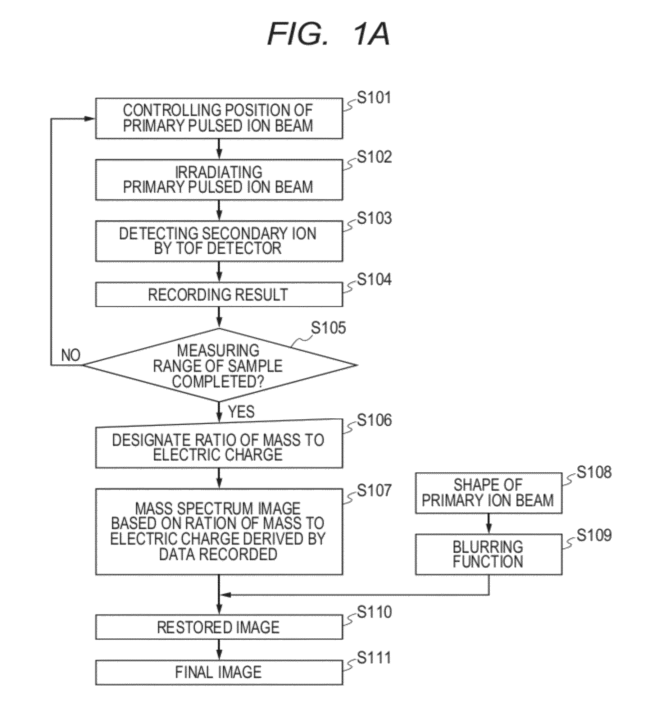
[0014]In the present invention, spread of a primary beam irradiated on a sample is calculated through a numeric or practical experiment process in TOF-SIMS, and a blurring function is used to restore an image and to reduce blur.
[0016]According to an image blur reduction method of a mass spectrum image derived by TOF-SIMS of the present invention, an estimated blurring function is used to execute image processing to reduce image blur of the mass spectrum image, and a clear image can be obtained.

Problems solved by technology

An issue is to provide a blur reduction method of a mass spectrum image derived by TOF-SIMS.

Method used


Image

  • Image processing method
  • Image processing method
  • Image processing method

Examples


example 1

[0051]To indirectly calculate the spread of the primary ion beam, a pulsed primary ion beam is irradiated on a smooth silicon substrate, and the shape of a crater generated by sputtering is measured.

[0052]FIG. 5 is an optical microscopic image of the crater formed by continuously applying the primary ion beam to the same part of the smooth silicon substrate. The size of the image is 40.76 μm long×40.76 μm wide. The image density is approximately proportional to the number of primary ions, because the image is a sputter mark based on the primary ion beam. Thus, the image can be used as a blurring function.

[0053]FIG. 6 is a mass spectrum image of a copper grid derived from an area of 66.27 μm long×66.27 μm wide. In the image, the brightly displayed part indicates copper.

[0054]The mass spectrum image illustrated in FIG. 6 is restored in accordance with FIGS. 4A and 4B based on the blurring function illustrated in FIG. 5.

[0055]Image processing software ImageJ developed by the

[0056]Natio...

example 2

[0063]In the SIMS using the TOF detector, the secondary ions need to be generated by simultaneously irradiating the sample with the primary ion beam to realize high mass resolution. Therefore, the pulse width of the primary ion beam is shortened so that a plurality of primary ions is incident in the surface of the sample at the same time.

[0064]The beam bunching is used to shorten the pulse of the primary ion beam. The beam bunching denotes convergence of the beam in the travelling direction to shorten the pulse. A beam bunching mechanism is usually incorporated into the primary ion beam irradiation system in the SIMS. The beam bunching mechanism simultaneously irradiates the surface of the sample with the short pulse primary ions. As a result, high secondary ion intensity is obtained, and the mass resolution improves.

[0065]As illustrated in FIG. 9, the primary ion beam irradiation system of the TOF-SIMS includes an ion source 4, a pulsing mechanism 5, a beam bunching mechanism 6, an...


PUM


Abstract

In a time of flight type secondary ionization mass spectrometry apparatus, spread of a primary beam irradiated on a sample is calculated through a numeric or practical experiment process, and the spread is used as a blurring function to restore an image to reduce blur. Provided is an image processing method of a mass spectrum image derived by irradiating a surface of a sample with a converged short pulsed primary beam, while changing an irradiating position, to display two-dimensionally a signal intensity based on a ratio of mass to an electric charge relating to a mass spectrum, derived by a time-of-flight secondary ion mass spectrometer, wherein the method comprising steps of: calculating a blurring function based on a shape of the primary beam incident in the surface of the sample; and restoring the mass spectrum image based on the blurring function.

Description

TECHNICAL FIELD[0001]The present invention relates to a blur reduction method of a mass spectrum image derived by a time-of-flight secondary ion mass spectrometry apparatus.BACKGROUND ART[0002]Methods of ionization without cleaving molecular compounds, such as a laser desorption / ionization method (LDI) and a matrix-assisted laser desorption / ionization method (MALDI), are put into practical use, and mass spectrometry is widely used particularly in a field of life science. Furthermore, mass spectrum imaging, which is a method of two-dimensionally deriving a mass spectrum based on mass spectrometry while changing an irradiating position of laser, is drawing attention. A secondary ion mass spectrometry (SIMS) has advantages because sample preparation is simple and high lateral resolution can be carried out a converged primary ions beam. The SIMS is an ionization method for ionizing atoms and molecules by irradiating a sample with primary ions. A time-of-flight (TOF) mass spectrometer, w...

Claims


Application Information

Patent Timeline
Patent Type & Authority Applications(United States)
IPC IPC(8): G06K9/40
CPCG06T5/003G06T2207/10056G06T2207/30024H01J2237/2527H01J2237/0432H01J2237/24585H01J49/0004G06T5/73
Inventor SUGA, TAKEO
Owner CANON KK
Learn More