
Method and system for receiving radio stations

a radio station and receiver technology, applied in the field of receiving radio stations, can solve the problems of unsatisfactory construction cost and greatly reduced bandwidth of the receiver, and achieve the effect of improving the combination of signals of different transmitting frequencies

Active Publication Date: 2012-11-29
ROBERT BOSCH GMBH
View PDF4 Cites 1 Cited by
  • Summary
  • Abstract
  • Description
  • Claims
  • Application Information

AI Technical Summary

Benefits of technology

[0015]Normally, one is able to receive a radio program on several transmitting frequencies fl to fN. The signals of these transmitting frequencies are able to be demodulated simultaneously in the digital signal processing unit, with the aid of a direct sampling system. Because of the combination of the signals of the various transmitting frequencies fl to fN, an improved receive signal may be achieved, compared to the reception of only one transmitting frequency.
[0019]However, it may definitely be of advantage if the switching over takes place by cross-fading the two signals.
[0020]According to a further preferred specific embodiment of the present invention, at least two or even more signals of different transmitting frequencies of a radio station are combined with one another to form a signal. An improved receive signal may be received in this way.
[0021]In this context, it may be provided, according to one preferred specific embodiment, that the combined signals are weighted differently. This is able to lead to a still better radio reception.
[0026]Furthermore, the combination of the signals of different transmitting frequencies may be even further improved if an adjustment of the amplitudes of the signals, for instance, of the swing of the signals is carried out after the demodulation.

Problems solved by technology

One disadvantage of the tuner assemblies known from the related art is that, before the digitization of the signal, its bandwidth is greatly reduced, so that to receive two or more signals, that is, two or more stations, one has to use a complete receiver path made up of a tuner assembly and A / D converter per signal to be received, respectively.
This represents a constructional increased cost that is not desirable.

Method used


Image

  • Method and system for receiving radio stations
  • Method and system for receiving radio stations

Examples


Embodiment Construction

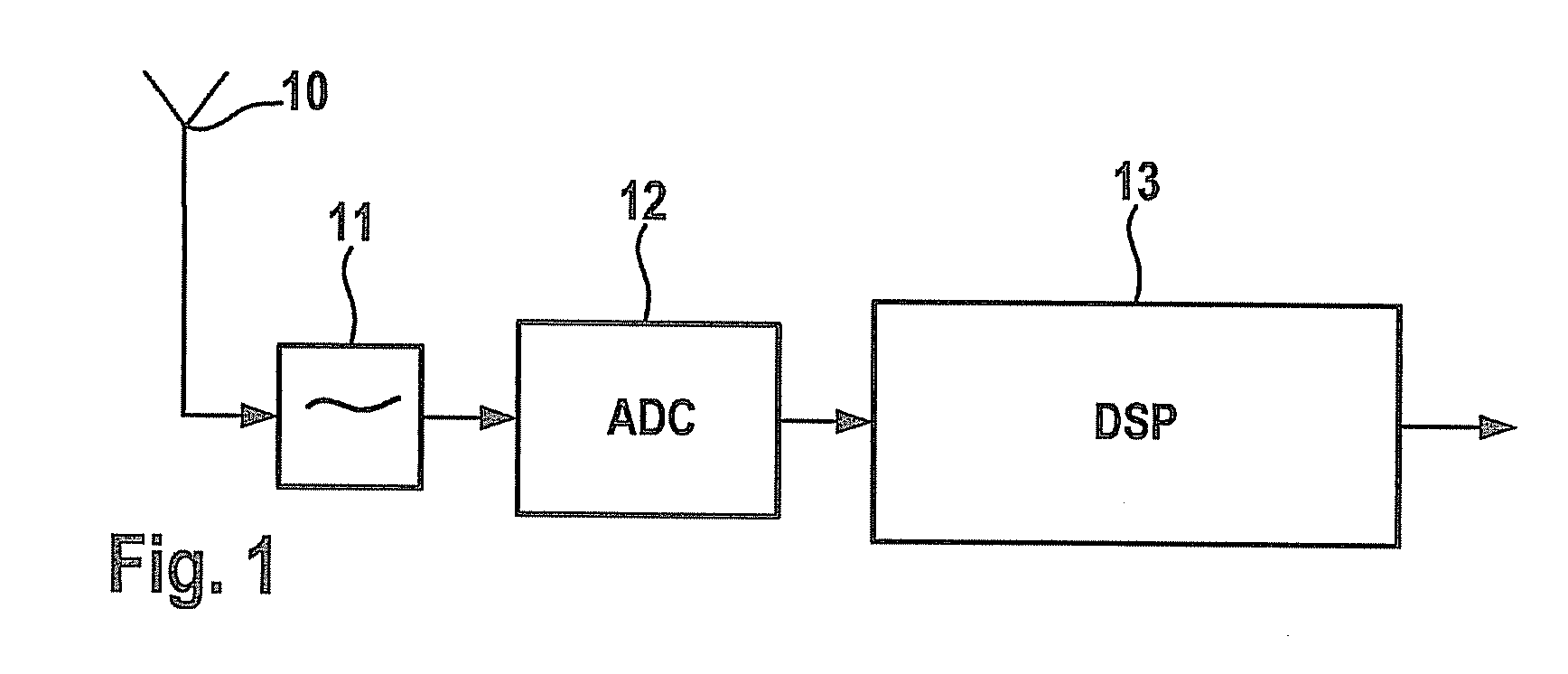
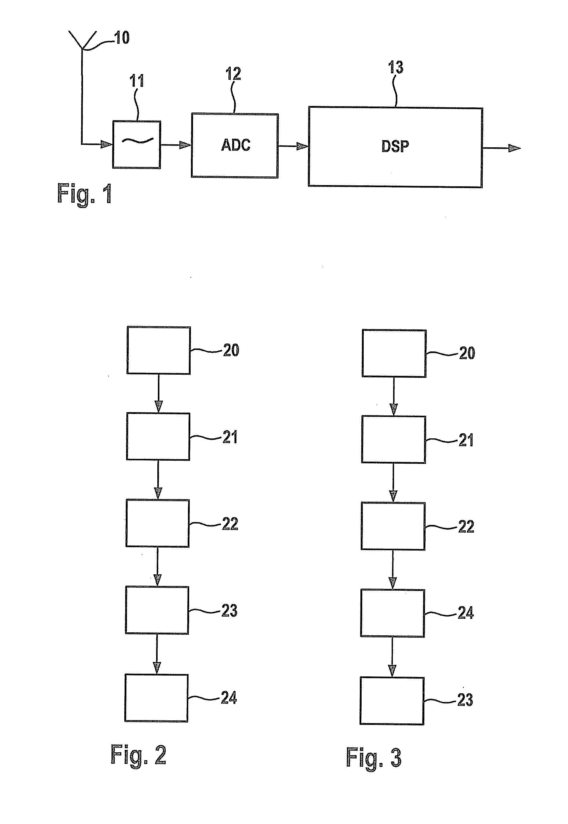
[0034]In an exemplary manner, FIG. 1 shows a system for the direct sampling of the entire FM band of a car radio receiver. The system includes an antenna 10, an HF preselector stage 11, an A / D converter 12 and a digital signal processing unit 13. HF preselector stage 11 includes, for instance, a band filter, in this context, possibly an amplifier and an AGC. Digital signal processing unit 13 may be a DSP, in this instance, and in it, as a function of the available calculating power, any desired number of channels of a radio station are able to be demodulated.

[0035]The flow chart of FIG. 2 shows a method for receiving radio stations according to a particularly preferred specific embodiment.

[0036]In FIG. 2 one may infer that first a frequency band is received 20, for instance, by an antenna. In an additional step, this received frequency band is then filtered using an HF preselector stage and perhaps amplified 21. The entire frequency band is then digitized 22 with the aid of a broadb...


PUM


Abstract

A system for receiving radio stations includes: at least one A / D converter in order to digitize the entire desired frequency band, for instance, an FM band, received via at least one antenna, and a demodulation unit for demodulating at least two signals of different transmitting frequencies of a radio station.

Description

BACKGROUND OF THE INVENTION[0001]1. Field of the Invention[0002]The present invention relates to a method and a system for receiving radio stations, including at least one A / D converter, in order to digitize the entire desired frequency band, such as the FM band, received over at least one antenna.[0003]2. Description of the Related Art[0004]In FM radio receivers used these days, tuner assemblies are included which are suitable for filtering the HF signal, incoming at the antenna of the radio, amplifying it and mixing it to a suitable intermediate frequency, such as 10.7 MHz. This is followed either by an analog demodulation of the signal or the signal is digitized using an A / D converter and then digitally demodulated.[0005]Thus, it is known, for example, from U.S. Pat. No. 6,334,051 B1 and published international patent application document WO 2009 / 021247 A1, that one may convert two or more radio signals A / D and select the respective required signal.[0006]One disadvantage of the t...

Claims


Application Information

Patent Timeline
Patent Type & Authority Applications(United States)
IPC IPC(8): H04L27/00
CPCH04B1/0007H04B1/0053H04B1/0092H04B7/12H04B7/084H04B7/0885H04B7/028
Inventor LEHR, CARSTENNYENHUIS, DETLEVRISSE, MARCUS
Owner ROBERT BOSCH GMBH
Learn More