Deboning method and apparatus for meat with bone using x-ray

a deboning method and bone technology, applied in meat deboning, poultry processing, testing water, etc., can solve the problems of reducing the capacity and power of the drive device of the cutting blade, and achieve the effects of preventing excessive load in the cutting blade, preventing excessive load, and reducing the yield of mea

Active Publication Date: 2012-11-22
MAYEKAWA MFG CO LTD
View PDF0 Cites 11 Cited by
  • Summary
  • Abstract
  • Description
  • Claims
  • Application Information

AI Technical Summary

Benefits of technology

[0029]Thus, since the reaction force applied to the cutting blade is measured and the operation course is corrected in the operation course change unit on the basis of the reaction force data, it is possible to further precisely operate the cutting blade along the surface of the bone. As a result, it is possible to further improve the yield of meat, avert the excessive load applied to the cutting blade, and avert the breakage of the blade and the cutting of the bone.
[0030]In the apparatus of the present invention, it is preferable that the controller sets a check point at a position where an excessive load tends to be generated in the cutting blade on the operation course of the cutting blade, the reaction force measurement device measures the reaction force applied to the cutting blade during the cutting operation in a region on an upstream side of the check point and, when the difference between the measured reaction force and the target reaction force data is out of the set range, the operation course change unit changes the corrected operation course from a point, where the reaction force is measured, to the check point such that the difference falls within the set range. By setting the check point at the joint part or the condyle part where many uneven variation points are present, it is possible to prevent the generation of the excessive load in the cutting blade beforehand, and also prevent the cutting of the cutting blade into the bone, the damage to the cutting blade, and the cutting of the bone.
[0031]The controller of the apparatus of the present invention preferably stores measurement data on a reaction force applied to the cutting blade during a no-load operation in the storage unit, and preferably further includes a determination unit that compares the reaction force applied to the cutting blade during the cutting operation of the cutting blade and the stored no-load reaction force data and, when a difference between the reaction force and the stored no-load reaction force data is out of a set range, determines that the cutting blade is damaged to issue an operation halt instruction. With this, it is possible to speedily detect the damage to the cutting blade to halt the operation of the deboning apparatus. Note that the set range is different from the set range for the difference between the measured reaction force and the target reaction force data, and is a range that is separately set.
[0032]According to the method of the present invention, since a method in which, in a state where an arm part or a thigh part of a carcass is suspended via an ankle, a deboning process of the arm part or the thigh part is performed by using a multi-axis articulated arm provided with a cutting blade that operates based on a predetermined operation course includes a preliminary step of setting a comparison reference point on an outline of a bone of the arm part or the thigh part, and also presetting three-dimensional position coordinates of a target operation course of the cutting blade and two-dimensional position coordinates of the comparison reference point corresponding to the three-dimensional position coordinates of the target operation course, an X-ray image analysis step of irradiating the X-ray to each arm part or each thigh part to obtain two-dimensional position coordinates of the outline of the bone of the arm part or the thigh part by analyzing a transmitted X-ray image, an operation course correction step of determining a positional displacement amount between t

Problems solved by technology

In addition, it is possible to avert the generation of an excessive load in the cutting blade, a

Method used


Image

  • Deboning method and apparatus for meat with bone using x-ray
  • Deboning method and apparatus for meat with bone using x-ray
  • Deboning method and apparatus for meat with bone using x-ray

Examples


second embodiment

[0131]Next, a description is given of a second embodiment in which the present invention is applied to the deboning step of a pig arm part on the basis of FIGS. 29 and 30. FIG. 29 shows preliminary process steps manually performed by an operator, and FIG. 30 shows deboning steps by an automatic deboning apparatus. In FIG. 29, the skeleton of an arm / shoulder part 110 after a dressed carcass is roughly divided is constituted by a backbone 112, a rib 114, a spur 116, a humerus 118, and a forearm bone 120. The arm / shoulder part 110 is divided along a cutting line C6 into an arm part 122 and a boston butt part 124. The boston butt part 124 divided from the arm part 122 is subjected to another deboning step. As for the arm part 122, a fat layer 126 in a neck part of the arm part 122 is removed in the next step, and then a rib meat 128 on the boundary side of the shoulder part is turned over. Next, an upper side meat 132 on a scapula 130 is torn.

[0132]Subsequently, as shown in FIG. 30, a s...


PUM


Abstract

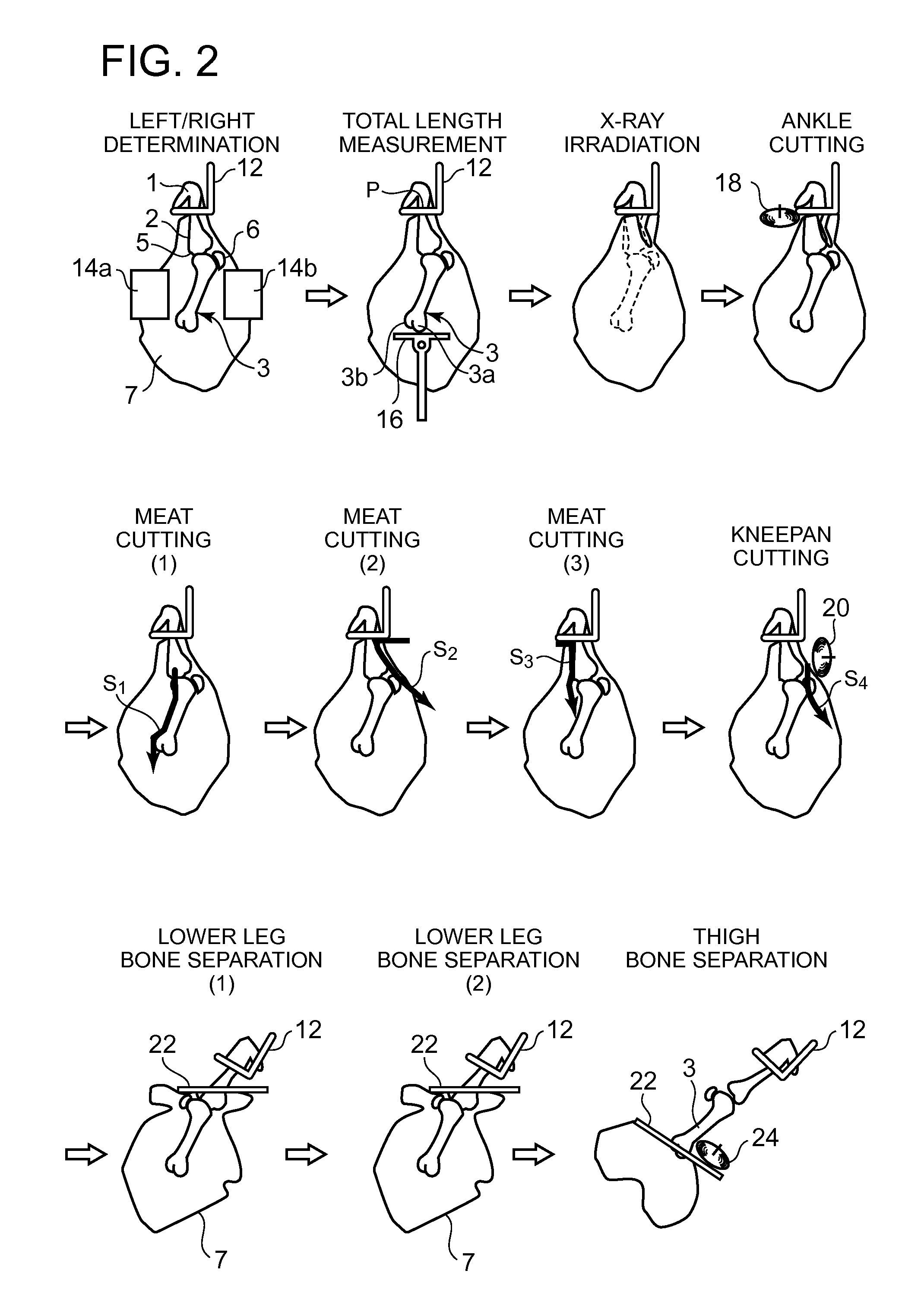
In an automatic deboning apparatus, an X-ray irradiation unit is provided on the upstream side of a meat cutting unit in a direction of transport of the work. In the X-ray irradiation unit, an X-ray r is irradiated to a work w from an X-ray irradiation device, an image of the X-ray transmitted through the work is subjected to image processing in an image analysis process unit, and two-dimensional position coordinates of a bone part are thereby obtained. In the meat cutting unit, three robot arms are provided with cutting blades. A storage unit of a controller stores three-dimensional position coordinates of a target operation course of each of the cutting blades. The target operation course is corrected on the basis of the two-dimensional position coordinates of the bone part obtained for each work in the image analysis process unit.

Description

TECHNICAL FIELD[0001]The present invention relates to a deboning method and a deboning apparatus that exhibit excellent yield and can avert damage to a cutting blade or the like by precisely grasping the outline of a bone by using an X-ray in the step of separating meat from the bone of an arm part or a thigh part of a carcass to be supplied as meat.BACKGROUND ART[0002]The step of deboning an arm part or a thigh part (hereinafter referred to as a “work”) of a carcass to be supplied as meat such as pork, beef, and mutton roughly consists of a preliminary step of removing a hip bone and the like, a meat cutting step of making a cut in a longitudinal direction along the surface of a forearm bone, a humerus, a lower leg bone, or a thigh bone, and a meat separation step of tearing meat after the meat cutting step. Because the work is heavy, when the dissection and deboning operation is manually performed, heavy work is required. As a result, an operator has performed the deboning process...

Claims


Application Information

Patent Timeline
IPC IPC(8): A22C17/00
CPCA22C17/004G01N33/1826G01N33/18A22C17/0086
Inventor HATTORI, KAZUHIROMURANAMI, HIROAKIUMINO, TATSUYAGOTO, OSAMUKIMURA, KENICHIRO
Owner MAYEKAWA MFG CO LTD
Why Eureka
Try Eureka