Working apparatus, in particular excavator or machine for material handling

Inactive Publication Date: 2012-11-22
LEIBHERR HYDRAULIKBAGGER GMBH
View PDF10 Cites 0 Cited by
  • Summary
  • Abstract
  • Description
  • Claims
  • Application Information

AI Technical Summary

Benefits of technology

[0021]The present disclosure further relates to a method of operating a working apparatus, in particular an excavator or a machine for material handling, having an element movable via at least one hydraulic working cylinder, wherein at least one energy recovery cylinder is provided for recovering energy from the movement of the movable element, said energy recovery cylinder being filled with gas at the base side and having an annular space filled with a medium. In accordance with the present disclosure, the method in this respect provides that the flow of the medium out of the annular space is restricted on an unwanted moving out of the piston rod. In this respect, in particular the flow of the medium out of the annular space is restricted when the piston rod is no longer mechanically secured due to a defect at the bearing points or at the bearing parts of the energy recovery cylinder or of the working apparatus so that the energy stored in the energy recovery cylinder would result in an uncontrolled moving out of the piston rod. The moving out of the piston rod is therefore also controlled by the inventive restriction of the flow of the medium out of the annular space in case of damage so that damage to the component and the environment are prevented. The energy recovery cylinder is in this respect advantageously designed and is operated as described above.

Problems solved by technology

In this respect, in particular the flow of the medium out of the annular space is restricted when the piston rod is no longer mechanically secured due to a defect at the bearing points or at the bearing parts of the energy recovery cylinder or of the working apparatus so that the energy stored in the energy recovery cylinder would result in an uncontrolled moving out of the piston rod.

Method used


Image

  • Working apparatus, in particular excavator or machine for material handling
  • Working apparatus, in particular excavator or machine for material handling
  • Working apparatus, in particular excavator or machine for material handling

Examples


first embodiment

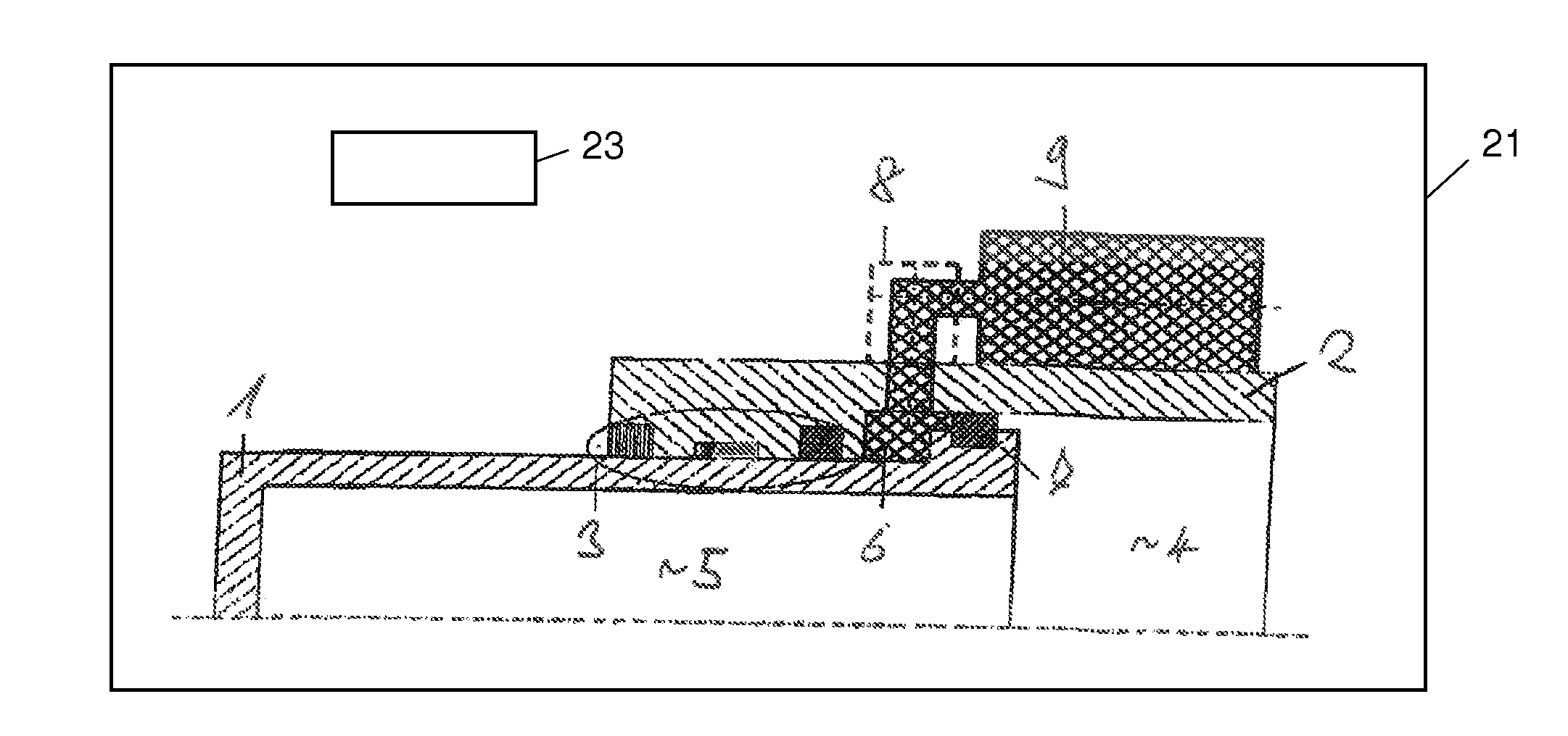
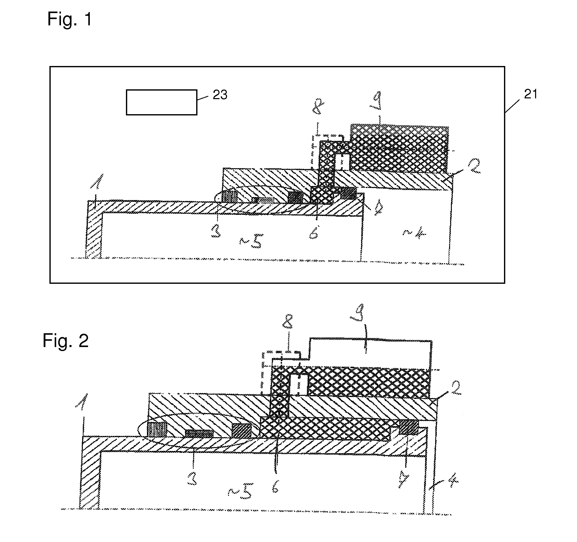
[0030]In the present disclosure shown in FIGS. 1 and 2, the annular space 6 is filled with a non-compressible medium, for example hydraulic oil. In this respect, the annular space 6 is in communication with an external container 9 via a flow restriction element 8. If the pressurized energy recovery cylinder can expand in an uncontrolled manner, e.g. due to a defect in the bearing points, the medium located in the annular space 6 has to flow through the flow restriction element into the external container 9. It is hereby no longer possible for the cylinder to expand in an uncontrolled manner.

[0031]The flow restriction element advantageously has a restrictor, a diaphragm or a valve unit. In this respect, the flow speed can advantageously be set by the flow restriction element. The valve unit can in this respect in particular be a flow control valve or a burst pipe protection.

[0032]FIG. 1 in this respect shows the energy recovery cylinder in accordance with the present disclosure with ...

second embodiment

[0033]In the second embodiment shown in FIG. 3, the annular space 6 is, in contrast, filled with gas and is in communication with the base side 4 via the flow restriction element 10. The gas is hereby restricted on the overflow between the annular space 6 and the base side 4 so that an uncontrolled moving out of the piston rod 1 is likewise prevented. In this respect, a restrictor 10 is advantageously used as the flow restriction element. A check valve 11 is advantageously provided parallel hereto and allows a free flow of the gas from the base side 4 into the annular space 6.

[0034]The present disclosure thus ensures a controlled expansion or moving out of an energy recovery cylinder under high pressure when it is no longer mechanically secured due to a defect of a bearing part.

[0035]While only FIG. 1 shows the working apparatus 21 and working cylinder 23, such components may also be included in FIGS. 2 and 3.


PUM


Abstract

The present disclosure shows a working apparatus, in particular an excavator or a machine for material handling, having an element movable via at least one hydraulic working cylinder, wherein at least one energy recovery cylinder is provided for recovering energy from the movement of the movable element, said energy recovering cylinder being filled with gas at the base side and having an annular space filled with a medium. In this respect, a flow restricting element is provided which restricts the flow of the medium from the annular space on a sudden moving out of the piston rod.

Description

CROSS REFERENCE TO RELATED APPLICATION[0001]This application claims priority to German Patent Application No. 10 2011 106 260.6, entitled “Working apparatus, in particular excavator or machine for material handling”, filed May 18, 2011, which is hereby incorporated by reference in its entirety for all purposes.TECHNICAL FIELD[0002]The present disclosure relates to a working apparatus, in particular to an excavator or to a machine for material handling, having an element movable via at least one hydraulic working cylinder, wherein at least one energy recovery cylinder is provided for recovering energy from the movement of the movable element, said energy recovery cylinder being filled with gas at the base side and having an annular space filled with a medium.[0003]Such a working apparatus is known from DE 10 2008 034 582 A1 whose content is made the subject of the present application in full. The energy recovery cylinder is in this respect used, e.g., to store the potential energy on...

Claims


Application Information

Patent Timeline
IPC IPC(8): F01B23/00
CPCF16F9/063E02F9/2217
Inventor EGENRIEDER, PHILIPPLAVERGNE, HANS-PETER
Owner LEIBHERR HYDRAULIKBAGGER GMBH
Why Eureka
Try Eureka