
Tubular sensor for the detection of an analyte

Active Publication Date: 2010-05-06
ROCHE DIABETES CARE INC
View PDF22 Cites 11 Cited by
  • Summary
  • Abstract
  • Description
  • Claims
  • Application Information

AI Technical Summary

Benefits of technology

[0014]Illustrative embodiments of the sensor disclosed herein can be produced simply and cost-effectively by means of a reliable production method and can avoid the disadvantages of the sensors and methods known from the prior art. In particular, illustrative embodiments of the sensor described herein are intended to be easy to implant and well tolerated in the implanted state.

Problems solved by technology

However, this method has various disadvantages.
In the first place, this method is extremely complicated and entails several handling steps.
For many patients, particularly older people and children, these handling steps can often be carried out only with difficulty since the patients are restricted, for example, in terms of their motor ability and their visual acuity.
Furthermore, these method steps can be carried out discretely only in a few cases, which means, for example, that the patient's privacy is protected only to an inadequate extent when carrying out a measurement at the workplace.
Moreover, incorrect operation of the measurement method can easily lead to false measured values, in some cases with fatal consequences resulting from incorrect medication based on the measurement results.
However, because of the different diameter of these coaxial electrodes, these individual electrode surfaces differ in terms of their properties and are limited in number.
Although the coaxial design is described in US 2007 / 0027384 A1 as being particularly insensitive with respect to bending, in contrast to planar sensor constructions, the solid structure in itself entails a high degree of stiffness of the sensors, and bending may even alter the active electrode surface areas and thus greatly influence the measured values.
This structure has the disadvantage that the exact position of the individual electrodes may be undefined, since the spiral-shaped electrodes can move along a longitudinal axis of the sensors.
Moreover, the number of the electrodes thus configured is limited, which has the result, for example, that an averaging of the measured values obtained from several electrodes can be done only with difficulty using this structure.
Overall, the implantable sensors known from the prior art are extremely complicated as regards their structure and their production.
If it is assumed that these sensors are disposable sensors that can only be used for a short time (typically for about one week), then it is clear that the methods used in the sensors known from the prior art do not satisfy the requirements made of disposable articles.
However, such methods are not compatible with the production of cost-effective disposable articles.
In view of the small size of these electrodes, lithographic methods are likewise required for these, which again drives up the costs for producing such sensors.
The construction known from U.S. Pat. No. 5,299,571 is also technically complicated since, in addition to a tube with two inner lumens having to be produced, it is also necessary for a conventional sensor element, but one with miniaturized dimensions, to be inserted into one of these inner lumens.
Moreover, lithographic methods, in particular the etching of metal layers that is associated with these methods, are not always as reliable as is necessary for the production of medical products.
In particular, it can happen that individual electrodes are still connected to one another by “bridges”, such that the functionality of the sensors can easily be impaired or even completely prevented on account of production problems.

Method used


Image

  • Tubular sensor for the detection of an analyte
  • Tubular sensor for the detection of an analyte
  • Tubular sensor for the detection of an analyte

Examples


Embodiment Construction

[0061]For the purposes of describing and defining the present invention it is noted that terms like “preferably”, “commonly”, and “typically” are not utilized herein to limit the scope of the claimed invention or to imply that certain features are critical, essential, or even important to the structure or function of the claimed invention. Rather, these terms are merely intended to highlight alternative or additional features that may or may not be utilized in a particular embodiment of the present invention.

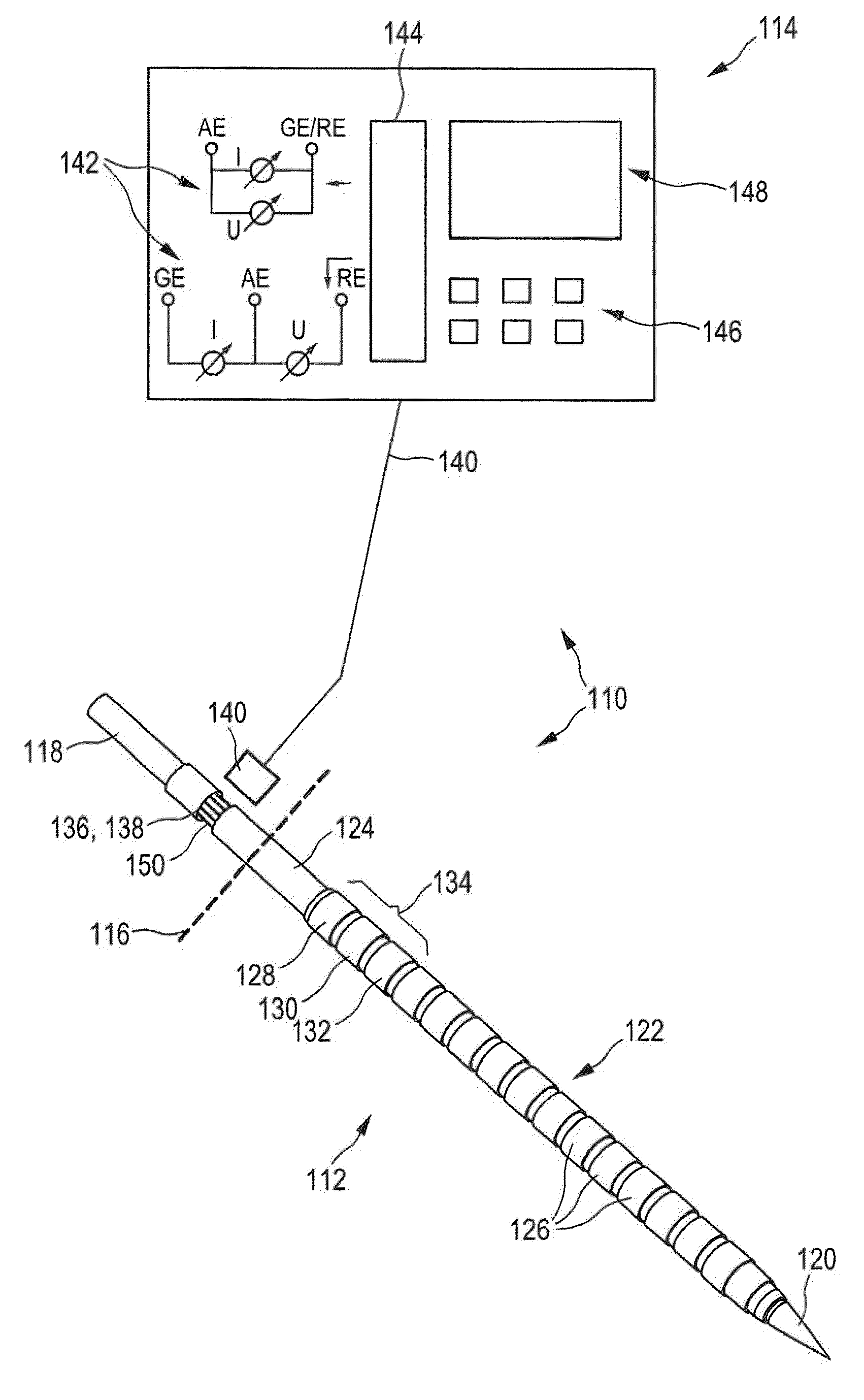
[0062]In FIG. 1, an illustrative embodiment of a sensor system 110 for determining a concentration of at least one analyte in a medium is shown in a highly schematic representation. The sensor system 110 comprises an implantable sensor 112 and an actuation and evaluation unit 114 connected to the implantable sensor 112.

[0063]It is assumed below, without limiting the scope of the invention, that the implantable sensor 112 is a glucose sensor that can be implanted in a body tissue...


PUM


Abstract

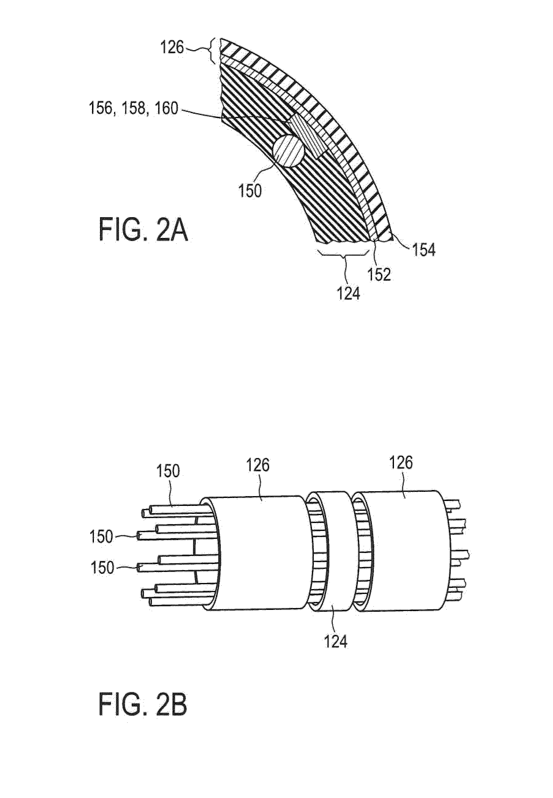
An implantable sensor can be used for determining a concentration of at least one analyte in a medium, particularly in a body tissue and / or a body fluid. The implantable sensor can comprise a flexible, tubular sensor element. This sensor element has a tubular body on which at least two electrode rings are mounted for electrochemical determination of the concentration of the analyte.

Description

CROSS-REFERENCES TO RELATED APPLICATIONS[0001]This application is a continuation of PCT Application No. PCT / EP2008 / 055233 filed Apr. 29, 2008, which claims priority to European Application Nos. 07107436.3, filed May 3, 2007, and 07116982.5, filed Sep. 21, 2007.FIELD OF THE INVENTION[0002]The invention relates to a subcutaneous sensor for determining a concentration of at least one analyte in a medium, particularly in a body tissue and / or a body fluid. The invention further relates to a sensor system and to a method for producing an implantable sensor. Such sensors or sensor systems are used particularly in the medical sector, for example for electrochemical determination of a concentration of blood glucose, triglycerides, lactate or other analytes.DESCRIPTION OF THE RELATED ART[0003]Determination of blood glucose concentrations and corresponding medication are an essential part of the daily routine of diabetics. The blood glucose concentration has to be determined quickly and simply...

Claims


Application Information

Patent Timeline
IPC IPC(8): A61B5/1473
CPCA61B5/14532A61B5/14546A61B5/6849A61B5/6848A61B5/14865
Inventor SCHWIND, KARINHAAR, HANS-PETERFUERST, OTTO
Owner ROCHE DIABETES CARE INC
Learn More