Ultrasonic imaging apparatus and method of controlling delay

a technology of ultrasonic imaging and delay, applied in the field of ultrasonic imaging apparatus, can solve the problems of increasing circuit scale, increasing apparatus cost, and huge circuit scale, and achieve the effects of simplifying explanation, convenient installation, and easy packaging

Active Publication Date: 2012-11-08
CANON KK
View PDF23 Cites 26 Cited by
  • Summary
  • Abstract
  • Description
  • Claims
  • Application Information

AI Technical Summary

Benefits of technology

[0018]According to the present invention, propagation time values corresponding to a plurality of focal points are calculated by recurrence relation for the depth direction of each receive channel, therefore the propagation time values can be calculated in parallel for a plurality of channels, and the delay time values can be calculated at high-speed.

Problems solved by technology

In any case, a number of delay time values to store increases, and the circuit scale become huge.
In both configurations, the circuit scale increases and the apparatus becomes expensive.
The MPU dedicated to numerical operation also causes an increase in scale and cost of the digital circuits for forming ultrasonic beams.
In this way according to U.S. Pat. No. 6,607,489, the scale of conventional digital circuits is increased, which makes the size and cost of the apparatus, and the processing speed and limits on resolution that can be set become inferior to prior art.
As a result, the advantages of a conventional ultrasonic diagnostic apparatus, which are real-time characteristics of image observation, and flexible diagnosis in a wide range implemented by a compact apparatus configuration, are diminished.
However if the dynamic receiving focus for changing the focal point in real-time is performed according to this method, the following problems remain.
But in the case of performing dynamic receiving focus, calculation using the recurrence relation must be performed for each focal point, and processing amount increases, therefore this method is not appropriate for real-time processing.
This problem becomes particularly conspicuous if many receive focal points are set to make resolution higher.
However in the case of processing according to WO 01-026555, the recurrence relation processing for resetting the delay time for all the transducers must be executed every time the receive focal point changes, as mentioned above, so this parallel processing operation cannot be used effectively.

Method used


Image

  • Ultrasonic imaging apparatus and method of controlling delay
  • Ultrasonic imaging apparatus and method of controlling delay
  • Ultrasonic imaging apparatus and method of controlling delay

Examples


example 1

[0095]A case of applying the present invention to an ultrasonic image diagnostic apparatus will now be described in detail using an example.

[0096]An ultrasonic image diagnostic apparatus (ultrasonic echo diagnostic apparatus) according to this example will now be described with reference to FIG. 1.

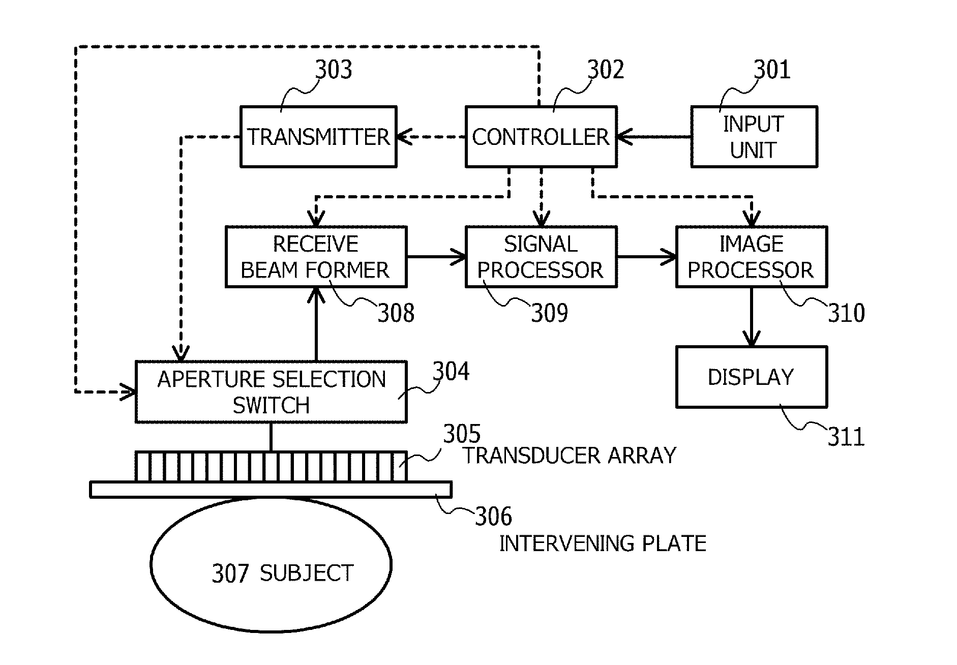
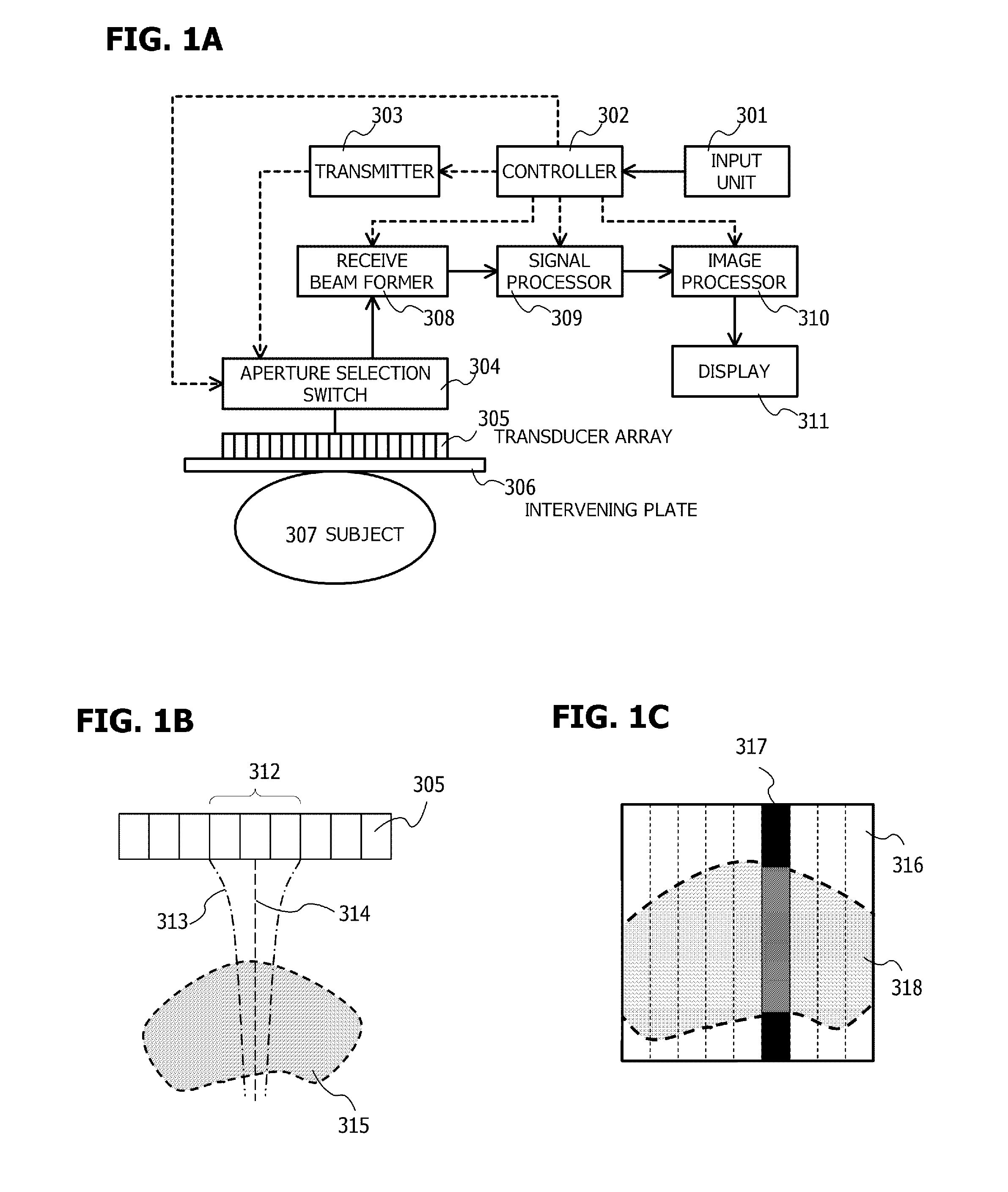
[0097]FIG. 1A shows a configuration of an ultrasonic imaging apparatus according to this example. FIG. 1B shows an ultrasonic beam used in the ultrasonic imaging apparatus according to this example. FIG. 1C shows an image or image data generated by the ultrasonic imaging apparatus corresponding to the ultrasonic beam shown in FIG. 1B.

[0098]In FIG. 1A, reference numeral 301 indicates an input unit, 302 indicates a controller, 303 indicates a transmitter, 304 indicates an aperture selection switch, 305 indicates a transducer array, 306 indicates an intervening plate, 307 indicates a subject, and 308 indicates a receive beam former. 309 indicates a signal processor, 310 indicates an image pro...

example 2

[0162]Example 2 of the present invention is an ultrasonic imaging apparatus based on a photoacoustic imaging method using photoacoustic waves. According to the photoacoustic imaging method, an internal structure of the subject is imaged by irradiating a pulse layer beam onto a subject, and detecting an ultrasonic wave, which is a photoacoustic wave induced by thermal expansion.

[0163]A concrete procedure of the photoacoustic imaging method is disclosed as follows, in the Japanese Patent Application Publication (Translation of PCT Application) No. 2001-507952, for example.

[0164](1) A two-dimensional transducer array (two-dimensional receiving element array) is positioned on the subject surface, and single pulsed electromagnetic energy is irradiated onto the subject.

[0165](2) A receive photoacoustic signal of each transducer (each receiving element) is sampled and stored immediately after irradiation of the electromagnetic energy.

[0166](3) Propagation time for the photoacoustic wave to...


PUM


Abstract

The present invention enables ultrasonic propagation time values after correction of refraction to be calculated in parallel for each receive channel, by using a recurrence relation in the depth direction. Moreover, accumulation of errors can be avoided by using an accurate propagation time value obtained in advance at a reference depth to correct the propagation time value each time the reference depth is reached. For this error correction, the recurrence relation to calculate the propagation time value can be an approximate expression. For example, the propagation time value can be calculated using the inclination of reference propagation time values between reference depths. In an actual circuit, received signals are sequentially stored in a memory, and a receive beam is formed by calculating an address position corresponding to the propagation time value of the ultrasonic wave, and adding the received signals stored in the calculated addresses.

Description

TECHNICAL FIELD[0001]The present invention relates to an ultrasonic imaging apparatus for receiving ultrasonic waves which are reflected or generated in a subject and for imaging the received ultrasonic waves, and more particularly to a digital ultrasonic imaging apparatus which performs delay correction, according to the ultrasonic propagation time, on signals obtained from a plurality of receiving elements for forming a receive beam.BACKGROUND ART[0002]Since ultrasonic waves do not cause exposure and are basically non-invasive, ultrasonic image diagnosis is widely used. Particularly in recent years, the delay time generated for forming an ultrasonic beam can be easily controlled at high precision because of the advancement of digitization of ultrasonic imaging apparatuses. By this, a high quality biological tomographic image can be obtained using a compact apparatus, which is used for the diagnosis of each area. In addition to an ultrasonic echo diagnostic apparatus which irradiat...

Claims


Application Information

Patent Timeline
Patent Type & Authority Applications(United States)
IPC IPC(8): G06K9/00
CPCG01S7/52034G10K11/346G01S7/52049
Inventor OIKAWA, KATSUYAYODA, HARUO
Owner CANON KK
Why Eureka
Try Eureka