
Ultrasound coupling device

a coupling device and ultrasonic technology, applied in ultrasonic/sonic/infrasonic diagnostics, applications, therapy, etc., can solve the problems of insufficient ultrasound bandages or coupling devices provided in the art to date for use with portable therapeutic ultrasound systems, and achieve efficient acoustic coupling

Inactive Publication Date: 2012-11-01
ZETROZ
View PDF5 Cites 39 Cited by
  • Summary
  • Abstract
  • Description
  • Claims
  • Application Information

AI Technical Summary

Benefits of technology

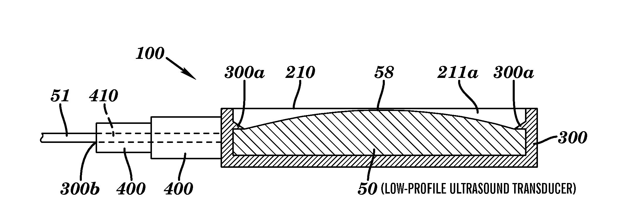
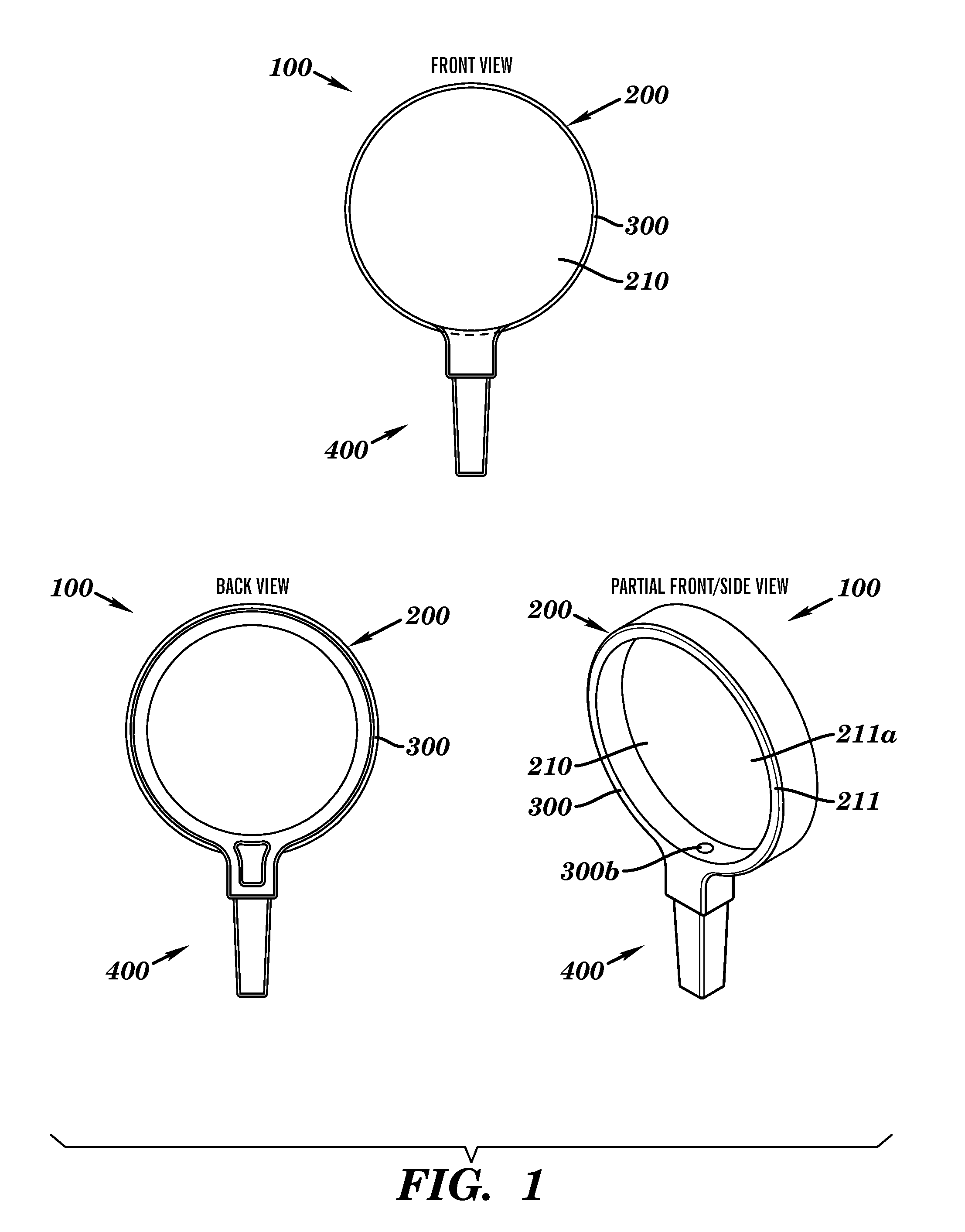
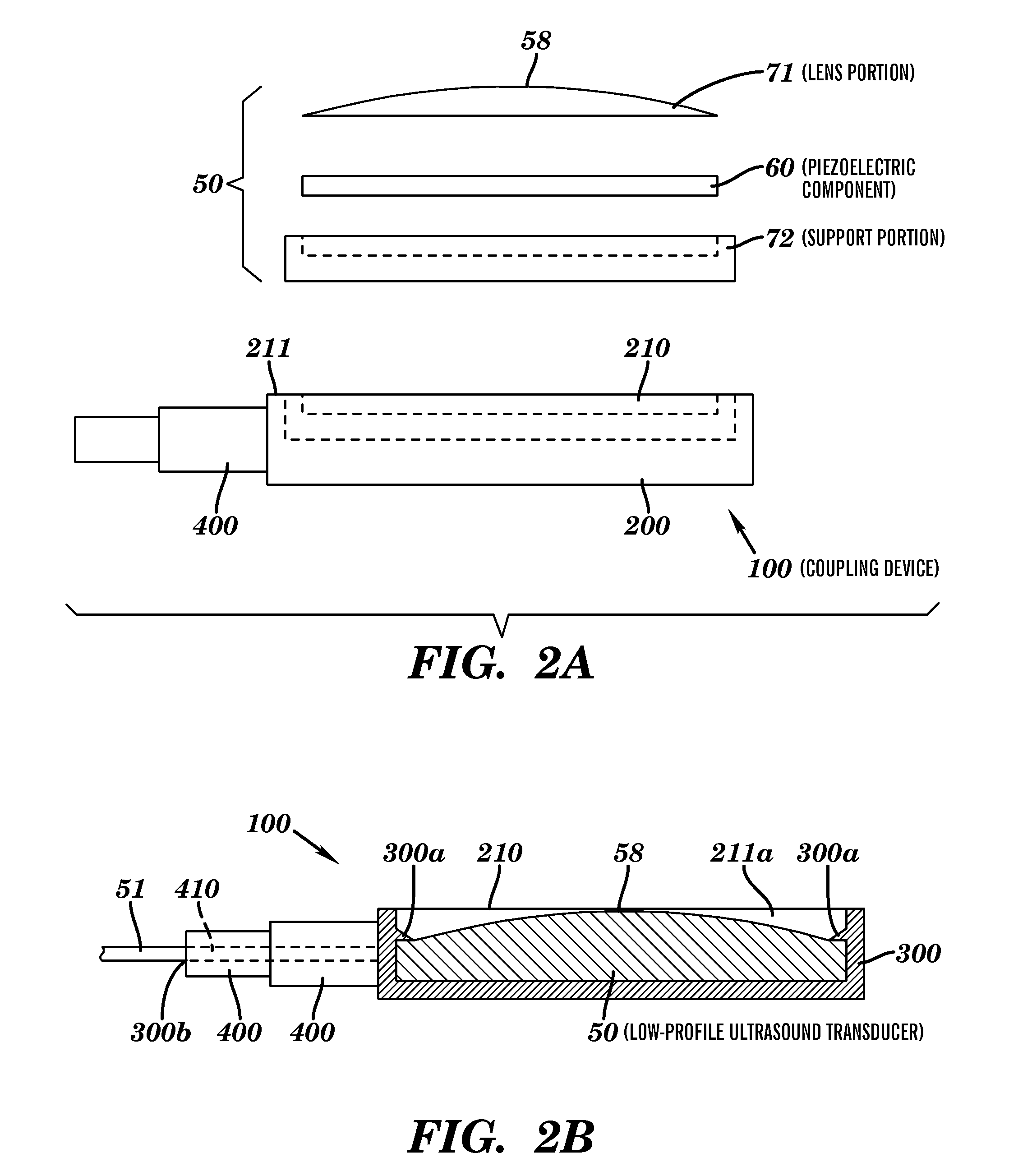
[0015]The ultrasound coupling device of the present invention is suitable for use with various ultrasound transducer systems. In one particular embodiment, the ultrasound coupling device is effective for use with a low-profile therapeutic ultrasound transducer.
[0016]For example, the ultrasound coupling device can be configured as an ultrasound transmission patch and be used as a means of temporarily holding an ultrasound transducer in place, and efficiently acoustically coupling the ultrasound transducer to another object (e.g., a human). In such an embodiment, the patch / coupling device can be similar to an adhesive bandage used to cover a cut; however, it may have an internal pouch that securely holds the transducer in place. Additionally, the pouch in the patch that the transducer is inserted into can have an ultrasound transmission medium (e.g., ultrasound gel), also referred to herein as an ultrasound conductive medium, that acoustically couples the ultrasound transducer from the patch to the body of interest. The patch allows for temporary placement and coupling of ultrasound transducers in a variety of configurations without the direct application of acoustic transmission medium to the body of interest.
[0018]Therefore, the present invention provides an ultrasound coupling device that is flexible for use with wearable, portable therapeutic ultrasound systems, as well as with standard in-office therapeutic ultrasound systems.

Problems solved by technology

Traditional therapeutic ultrasound generation technologies have a number of deficiencies that prohibit their use in portable ultrasound delivery devices.
Further, therapeutic ultrasound devices are generally not able to be used for long periods, due to safety concerns, the non-portable size of the devices or the need for external power sources.
However, the ultrasound bandages or coupling devices provided in the art to date are insufficient for use with portable therapeutic ultrasound systems that are able to deliver ultrasound energy deep within tissue and that can be used for long periods of time.

Method used


Image

  • Ultrasound coupling device
  • Ultrasound coupling device
  • Ultrasound coupling device

Examples


embodiment 1

[0071]One embodiment (referred to as Ultrasound Coupling Device Embodiment 1) is illustrated in FIGS. 7 and 8. In this embodiment, a material such as a non-woven fabric can be used in combination with a semi-permeable membrane to allow placement of an ultrasound transducer on an object. The transducer can be secured in place internally to the patch, and the semi-permeable membrane window allows efficient coupling of ultrasound energy from the transducer into the object (e.g., a human). This embodiment is generally configured in a “patch” or “bandage” configuration. The patch may be in a pouch that can prevent the gel inside of the pouch from drying out. Further, the front surface of the patch (the side that contacts the body) can have a laminate coating / plastic film that may be removed to expose the adhesive as well as the semi-permeable membrane. This mechanism is similar to how an adhesive bandage is produced.

[0072]Device Attributes. Ultrasound Coupling Device Embodiment 1 has var...

embodiment 2

[0074]One embodiment is further referred to as Ultrasound Coupling Device Embodiment 2. This embodiment is similar to Ultrasound Coupling Device Embodiment 1 (described herein). However, in Ultrasound Coupling Device Embodiment 2, the device is not in the form of a patch but of a semi-permeable membrane that may be used to effectively transmit ultrasound from an ultrasound transducer into a body (e.g., a human) without the need for applying ultrasound gel or other coupling medium to the surface of the object. Therefore, the invention reduces the aggravation and discomfort of using ultrasound devices.

[0075]Device Attributes. Ultrasound Coupling Device Embodiment 2 has various attributes, including, for example, the following: (i) this device can have a broad impact on improving ultrasound imaging and therapy applications by removing the gel; (ii) the transducer can slip into the device; (iii) the device can be filled with ultrasound gel; (iv) the membrane of the device can be configu...


PUM

PropertyMeasurementUnit
Pressureaaaaaaaaaa
Viscosityaaaaaaaaaa
Permeabilityaaaaaaaaaa

Abstract

The present invention relates to an ultrasound coupling device for use with various ultrasound transducers, systems, and applications. The coupling device includes a coupling compartment comprising a chamber having a continuous side wall and an opening on a first end. The continuous side wall is configured to hold a low-profile ultrasound transducer within the chamber so that a front ultrasound emitting surface of the low-profile ultrasound transducer faces outward toward the chamber opening. The front ultrasound emitting surface is configured to control the direction and wave pattern of ultrasonic energy emitted from the transducer. The continuous side wall is also configured to hold a quantity of an ultrasound conductive medium within the chamber and is operative to keep the ultrasound conductive medium in simultaneous contact with a surface of a subject and with at least a portion of the front ultrasound emitting surface of the transducer. The present invention also relates to an ultrasound apparatus, kit, and methods of using the ultrasound coupling device, apparatus, and kit.

Description

CROSS-REFERENCE TO RELATED APPLICATIONS[0001]This application claims priority benefit of U.S. Provisional Patent Application Ser. No. 61 / 291,732, filed Dec. 31, 2009, U.S. Provisional Patent Application Ser. No. 61 / 291,779, filed Dec. 31, 2009, and U.S. Provisional Patent Application Ser. No. 61 / 291,804, filed Dec. 31, 2009, the disclosures of which are hereby incorporated by reference herein in their entirety.FIELD OF THE INVENTION[0002]The present invention relates to an ultrasound coupling device, ultrasound apparatus, ultrasound kit, and methods of using the device, apparatus, and kit in various ultrasound applications.BACKGROUND OF THE INVENTION[0003]Traditional therapeutic ultrasound generation technologies have a number of deficiencies that prohibit their use in portable ultrasound delivery devices. For example, current therapeutic ultrasound generation technologies are generally, at the smallest, shoebox-sized devices that include a user interface, power generation circuitry...

Claims


Application Information

Patent Timeline
IPC IPC(8): A61N7/00A61M37/00
CPCA61B8/4281A61B17/2251Y10T29/49005A61N7/00A61N2007/0078A61B2017/2253A61B8/4227A61B8/4236A61B8/4427A61B2017/00734A61N2007/006A61N2007/0091A61N2007/0095A61B8/44A61B2034/301A61B34/30A61B2034/303A61B2034/107A61B34/10A61N2007/0034
Inventor LEWIS, JR., GEORGE K.GUFFEY, BRYANT
Owner ZETROZ
Learn More