
Cooled motor

a technology of cooling motors and motors, which is applied in the direction of motor/generator/converter stoppers, dynamo-electric converter control, instruments, etc., can solve the problems of user dissatisfaction with the product, product repair or replacement expense, and degrade the reliability and longevity of the shredder produ

Inactive Publication Date: 2012-11-01
AURORA OFFICE EQUIP
View PDF0 Cites 18 Cited by
  • Summary
  • Abstract
  • Description
  • Claims
  • Application Information

AI Technical Summary

Problems solved by technology

Such excessive or rough wear can, over time, degrade the reliability and longevity of the shredder product, causing the user to become dissatisfied with the product.
In some cases, repeated stresses on the moving parts of the shredder may cause part failure, leading to the expense of product repair or replacement, a further decrease in satisfaction, or even loss of goodwill for the respective purchaser in the paper shredder brand.
Even marginally stressful moments of operation may, in the aggregate, take their toll on the operating machinery of the shredder.
One shredder part which can be vulnerable to mechanical and thermal stresses is the shredder electric motor, which can arise from, for example, frequent starting; overloading; jamming; prolonged, unloaded operation; and continuous, beyond-rating use.
Unnecessary electrical usage also is undesirable.
Over time, the cumulative stresses faced by a shredder motor may lead to premature failure, or to poor performance.
However, in the sphere of fractional-horsepower electric motors, as used in light- to medium-duty paper shredders and industrial equipment, sophisticated electronic controllers and complex mechanical coolers can add prohibitive premiums to the motor cost, and to the cost to purchasers, reducing a manufacturer's market share.

Method used


Image

  • Cooled motor
  • Cooled motor
  • Cooled motor

Examples


Embodiment Construction

[0016]Embodiments of the present invention can assist in reducing overheating in a motor. In particular, selected embodiments can be used with a fractional horsepower (FHP) motor, as may be used without limitation, to power a light- or medium-duty office or industrial device. Some embodiments are passive devices, while some are active.

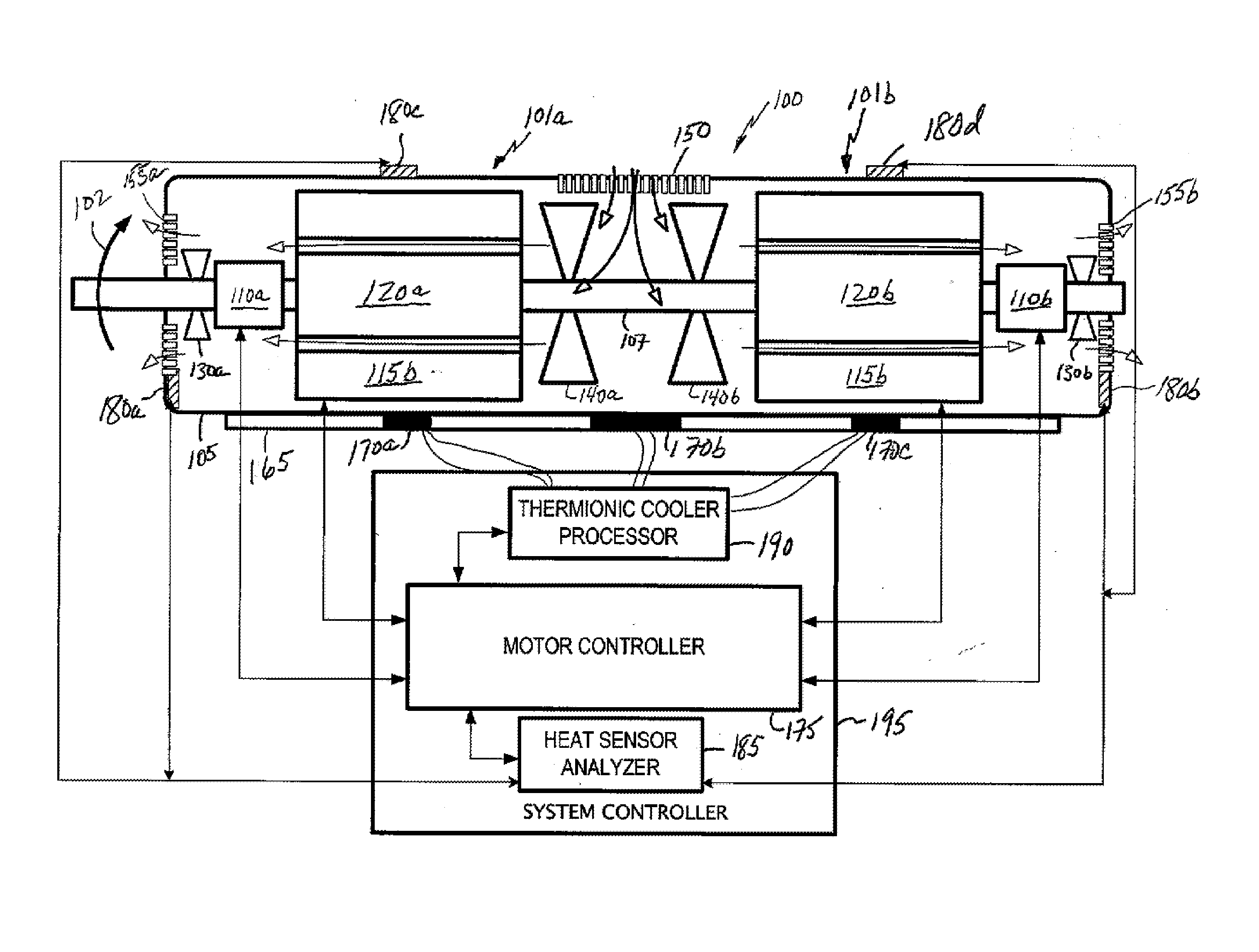
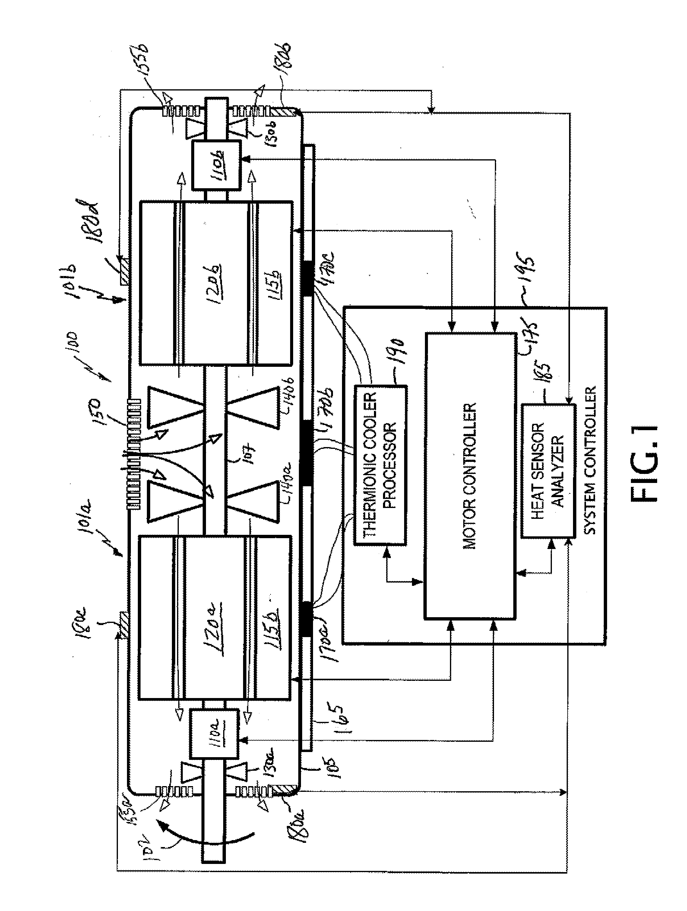
[0017]A universal motor in accordance with embodiments herein generally include a motor portion (101a) on the left side of a horizontal axis being mirrored by the motor portion (101b) on the right. The motor portions are enclosed in a ventilated casing 105, and employ a common rotor shaft 107. Accordingly, motor portions 101a, 101b respectively include a stator 115a, 115b, a rotor 120a, 120b, commutator 110a, 110b, commutator fan 130a, 130b, and rotor bearings 125a, 125b.

[0018]Although a universal series-wound type of motor is used to describe the innovations herein, embodiments may be used mutatis mutandi on an AC motor, a DC motor, a brushed motor, ...


PUM


Abstract

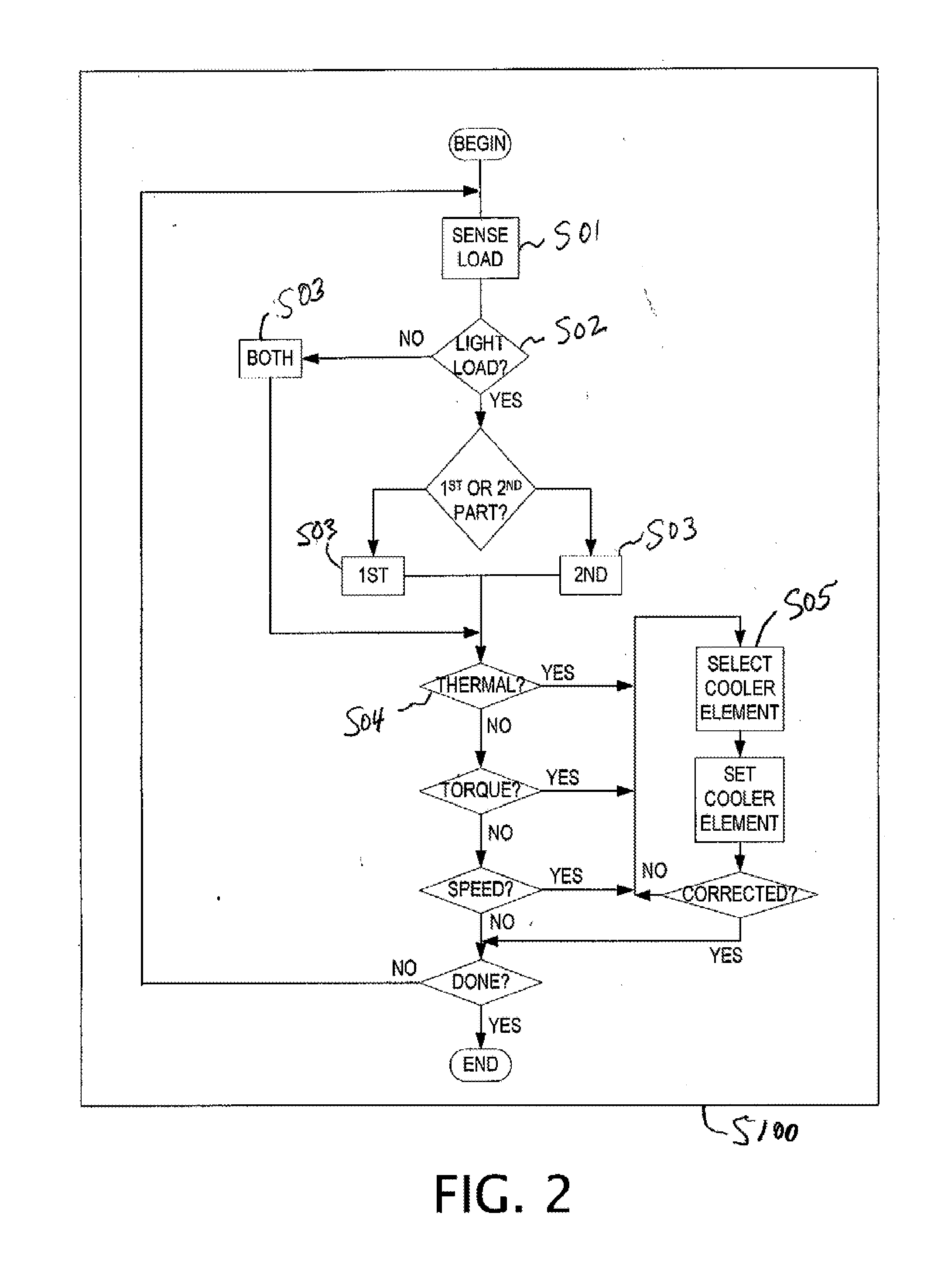
A motor having a first portion configured to turn in a forward direction, a second portion coaxially mirrors the first portion; and a central fan between the first and second portions, and forcing air through the portions. A thermoelectric cooler element, thermally coupled to the portion is configured to cool the motor. A motor controller is electrically coupled to the first and second portions, and operates a portion in response to a condition sensed by the motor controller. The condition sensed by the motor controller is a motor torque, a motor speed, a motor casing temperature, or a zoned motor casing temperature. A method includes detecting a motor operational command; selecting a motor operational state using motor portion responsive to the motor command; sensing a heating state of a motor portion; and providing a cooling state to the motor portion responsive to the heating state.

Description

BACKGROUND[0001]1. Field of the Invention[0002]The present invention relates to electric motors and more particularly to electric motors having cooling apparatus.[0003]2. Background Art[0004]Product satisfaction is driven at a particular product price point by product safety, product reliability, and product longevity. This is particularly so in the field of paper shredders, where a shredder can be expected to endure excessive or rough wear regardless of the heartiness of the shredder product specifications. Such excessive or rough wear can, over time, degrade the reliability and longevity of the shredder product, causing the user to become dissatisfied with the product. In some cases, repeated stresses on the moving parts of the shredder may cause part failure, leading to the expense of product repair or replacement, a further decrease in satisfaction, or even loss of goodwill for the respective purchaser in the paper shredder brand. Even marginally stressful moments of operation m...

Claims


Application Information

Patent Timeline
Patent Type & Authority Applications(United States)
IPC IPC(8): H02K9/06H02H7/085H02P1/22
CPCH02K9/22H02K9/06H02K9/227
Inventor O'ROURKE, JOHN
Owner AURORA OFFICE EQUIP
Learn More