Self-propelling sprue bar shutoff device

a sprue bar and shutoff device technology, applied in the field of injection molding machines, can solve the problems of loss of raw materials and additional cleanup costs, damage to equipment, and production loss, and achieve the effects of simple and robust construction, low viscosity, and reduced production cos

Inactive Publication Date: 2012-10-11
TRAKAS PANOS
View PDF3 Cites 0 Cited by
  • Summary
  • Abstract
  • Description
  • Claims
  • Application Information

AI Technical Summary

Benefits of technology

[0005]The present invention provides an improved self-propelling sprue bar shutoff device that reduces or eliminates drool.
[0008]Preferably, the movable body includes a non-ferromagnetic outer layer or shell and the magnet takes the form of a solid core which can move freely within the shell. The core will rotate until the magnetic poles thereof are in alignment with the magnetic field which passes through it and the ferromagnetic portion of the assembly block, thereby assuming proper operation and preventing jamming.

Problems solved by technology

Upon disconnection, molten polymer or “drool” will often be produced from the orifice of the sprue bar, resulting in the loss of raw material and additional cleanup costs.
If enough molten polymer drools from the sprue bar, it may solidify and prevent complete closure of the mold, causing damage to the equipment, expensive repairs, and lost production.
At the very least, this drooling effect requires removal by a technician, increasing the time between cycles.

Method used


Image

  • Self-propelling sprue bar shutoff device
  • Self-propelling sprue bar shutoff device
  • Self-propelling sprue bar shutoff device

Examples


Embodiment Construction

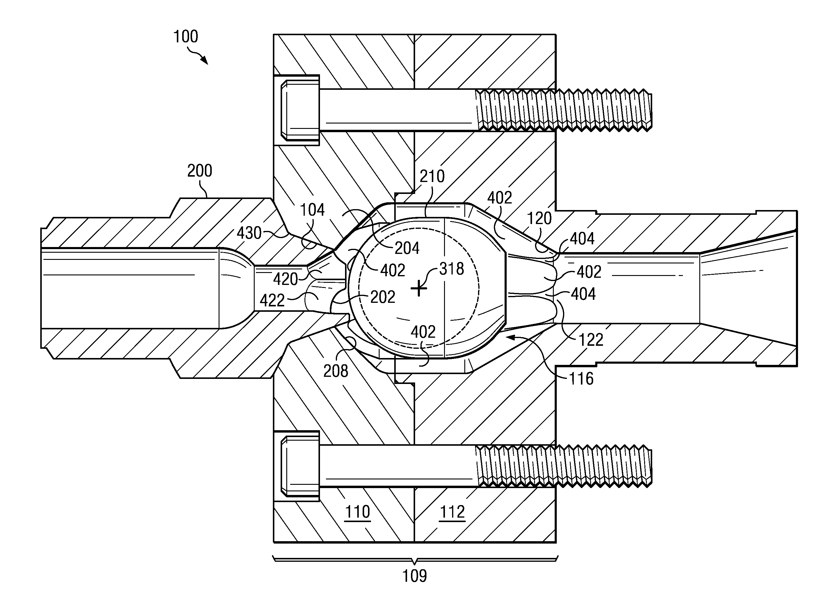
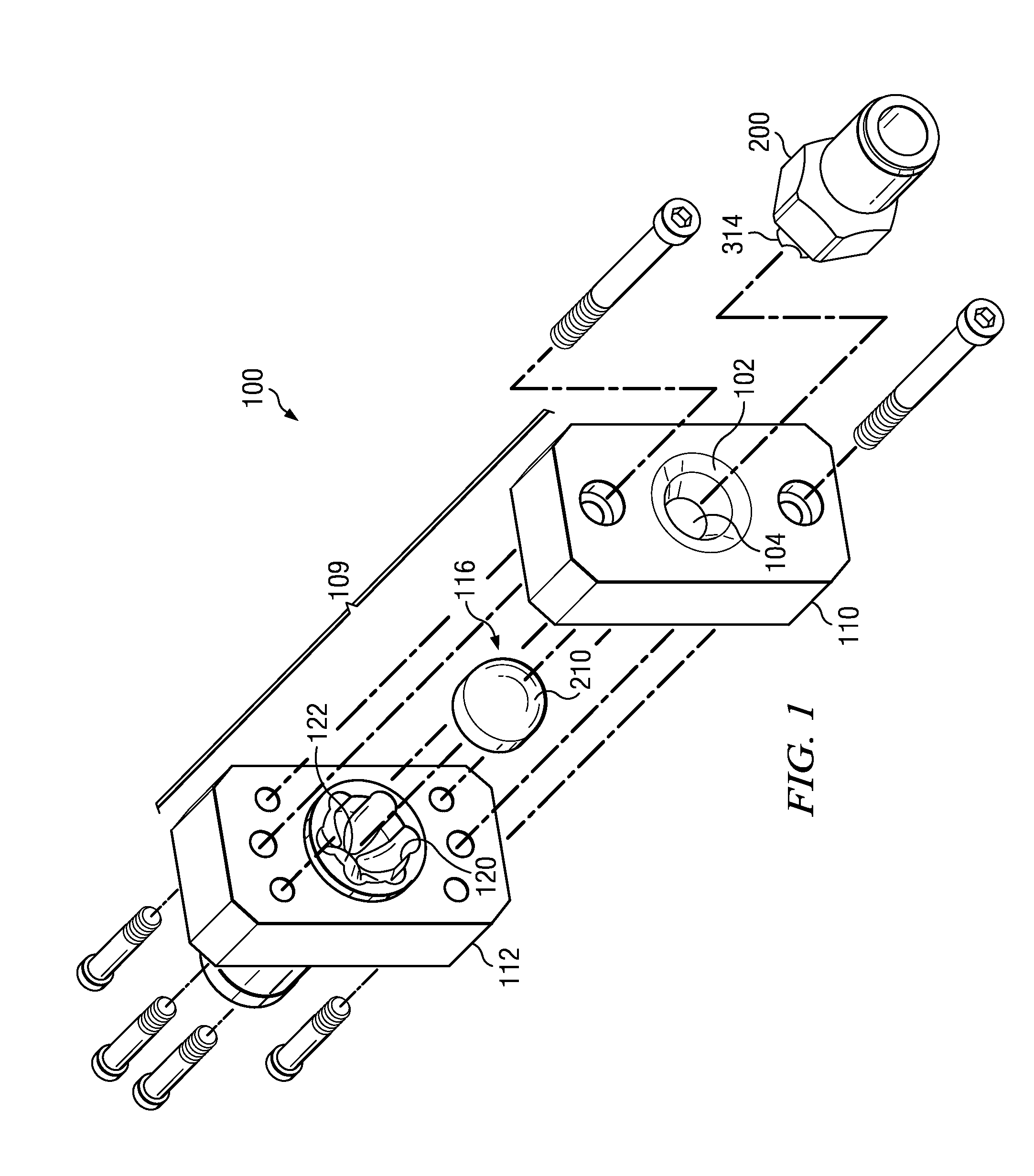
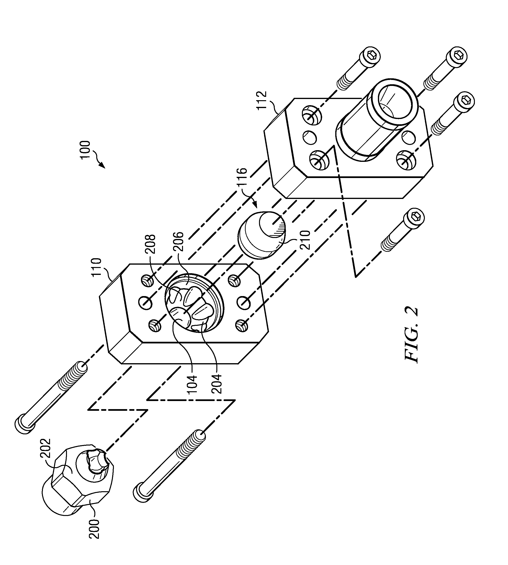
[0032]Referring to FIGS. 1, 2, 4A, and 4B, in a first embodiment of the invention, an injection mold shutoff assembly, indicated generally at 100, includes an assembly block 109. Block 109 defines a chamber 206 which has a rear end 406 and a forward end 408. Preferably, the assembly block 109 is made from at least a first assembly piece 110 and a second assembly piece 112. At least a portion of the first piece 110 is made of a ferromagnetic material, and the second piece 112 is made of a non-ferromagnetic (such as paramagnetic or diamagnetic) material. As used herein, a ferromagnetic material is one that is capable of forming a permanent magnet or is attracted to a magnet.

[0033]The assembly 100 further comprises an exterior seat 102 formed in the assembly block 109 near the rear end 406 of the chamber 206. More preferably, the exterior seat 102 is formed in the first piece 110 of the assembly block 109. The exterior seat 102 is sealable to a front mating surface 202 of an injection ...


PUM

PropertyMeasurementUnit
axial lengthaaaaaaaaaa
rotationaaaaaaaaaa
magnetic forceaaaaaaaaaa

Abstract

An injection molding shutoff assembly includes a chamber containing a movable body that is biased to a rear position in the chamber by a magnet in the movable body. In the rear position, the movable body provides a seal and prevents flow of molten plastic through the assembly. When the movable body is in a forward position, one or more passages permit flow of the molten plastic around the movable body and to an exit in the chamber, leading to one or more molds. An injection molding machine nozzle tip has a beveled front end which, when in an engaged position, seals with an exterior seat of the assembly block defining the chamber and protrudes into the chamber to prop the movable body to the forward position. A portion of the assembly block proximate the opening for the nozzle tip is made of ferromagnetic material, while the rest is not.

Description

BACKGROUND OF THE INVENTION[0001]The present invention relates to injection molding machines, and in particular, a shutoff device for use in a system that transports molten polymer from the molding machine to at least one stack mold by way of a sprue bar.[0002]It is known to provide stack molds in injection molding machines in which there are at least two sets of molding chambers which divide along separate parting lines. One method of delivering molten polymer to all of the molding chambers in a stack mold is by a sprue bar. A sprue bar extends from a sprue of the molding machine, along the axis of the stack mold assembly, to a central manifold located between at least two mold plates in the stack. A plurality of nozzles in turn provide conduits for the molten polymer from the manifold to each of the molding cavities, with some of the nozzles extending forward in an axial direction to those mold cavities which are forward of the manifold, and the rest of the nozzles extending rearw...

Claims


Application Information

Patent Timeline
Patent Type & Authority Applications(United States)
IPC IPC(8): B29C45/23B29C33/16
CPCB29C45/2758
Inventor TRAKAS, PANOS
Owner TRAKAS PANOS
Why Eureka
Try Eureka