
Camshaft phase shifting mechanism

a technology of phase shifting mechanism and camshaft, which is applied in the direction of non-mechanical valves, valve arrangements, yielding couplings, etc., can solve the problems of high oil demand, associated cost penalty, and problems with oil drainage and aeration, and achieves simple and robust construction. , the effect of fast response tim

Inactive Publication Date: 2005-05-19
MECHADYNE INT
View PDF3 Cites 5 Cited by
  • Summary
  • Abstract
  • Description
  • Claims
  • Application Information

AI Technical Summary

Benefits of technology

[0011] Because a single electromagnet can be used to bring about the desired change of phase, it is possible for the electromagnet to be fixed to the engine and to arrange for its magnetic circuit to traverse the fluid path, which must of necessity rotate with the camshaft. The fact that the electromagnet need not rotate with the camshaft makes for a simpler and more robust construction.

Problems solved by technology

While these phasers have been demonstrated to be effective, they can have a high oil demand, sometimes requiring an auxiliary pump and an associated cost penalty.
The presence of large amounts of oil in the engine cylinder head can cause problems with oil drainage and aeration, together with the problems associated with belt contamination in the case of belt driven camshafts.
Furthermore, the use of hydraulic actuation requires a control valve, which can control the oil flow in response to electrical inputs from the engine ECU, and this can have significant cost and packaging implications.

Method used


Image

  • Camshaft phase shifting mechanism
  • Camshaft phase shifting mechanism
  • Camshaft phase shifting mechanism

Examples


Embodiment Construction

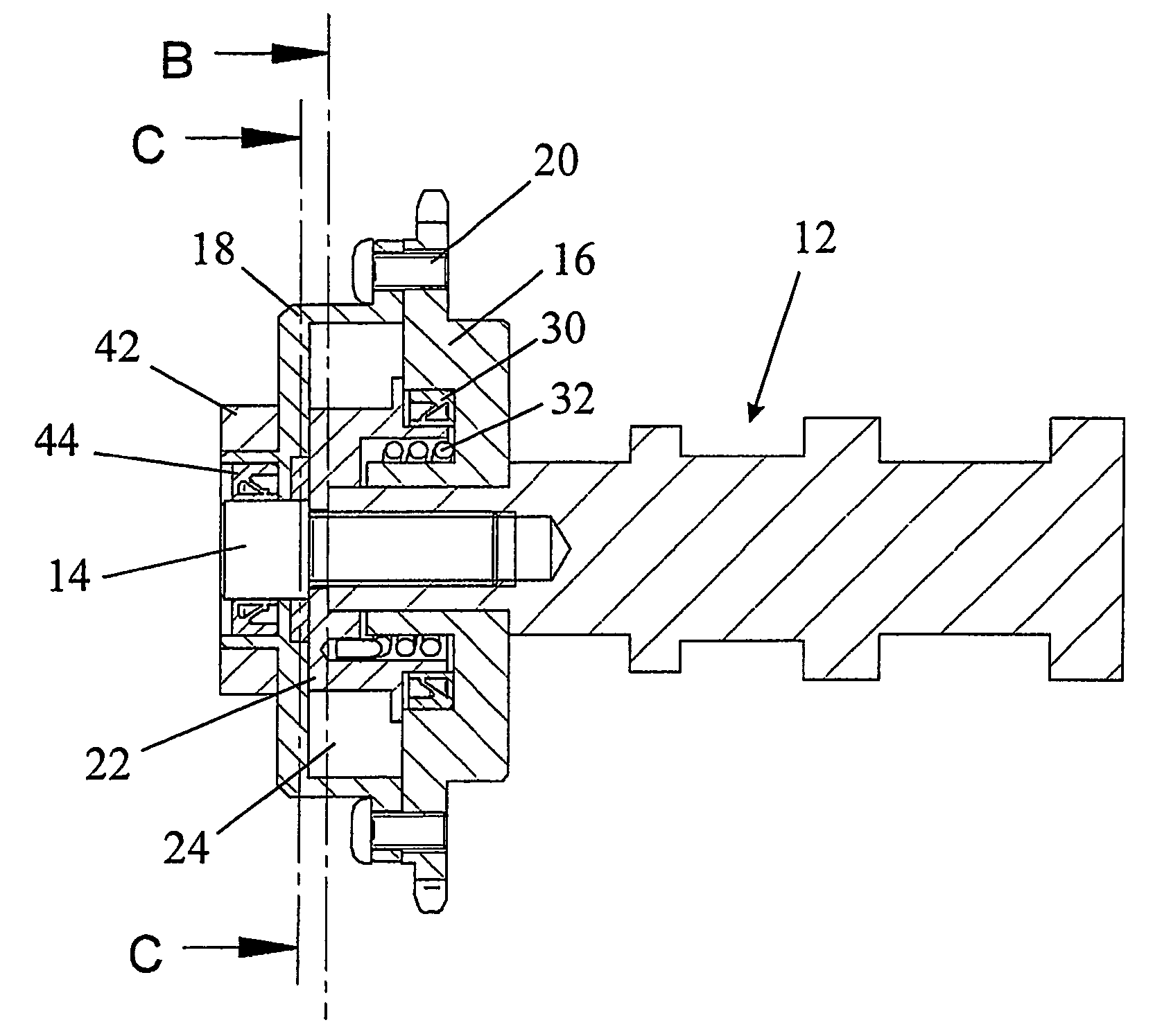
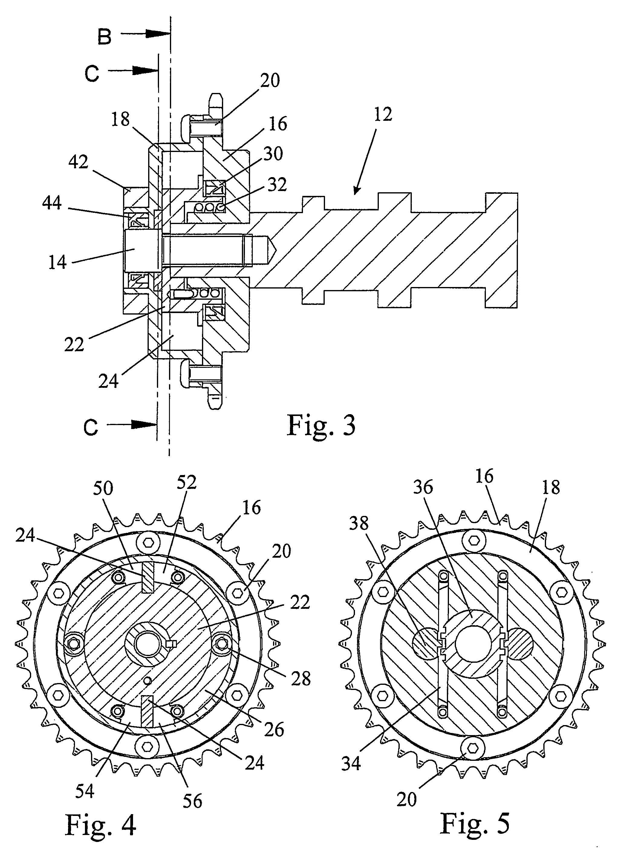
[0020] The illustrated phaser is similar in construction to the vane-type phasing systems that are often utilised in hydraulically controlled applications. The illustrated embodiment has two vane cavities but it will be appreciated by the person skilled in the art that many other layouts would clearly be possible. The phaser moves under the influence of camshaft torque reversals and hence requires no external source of energy.

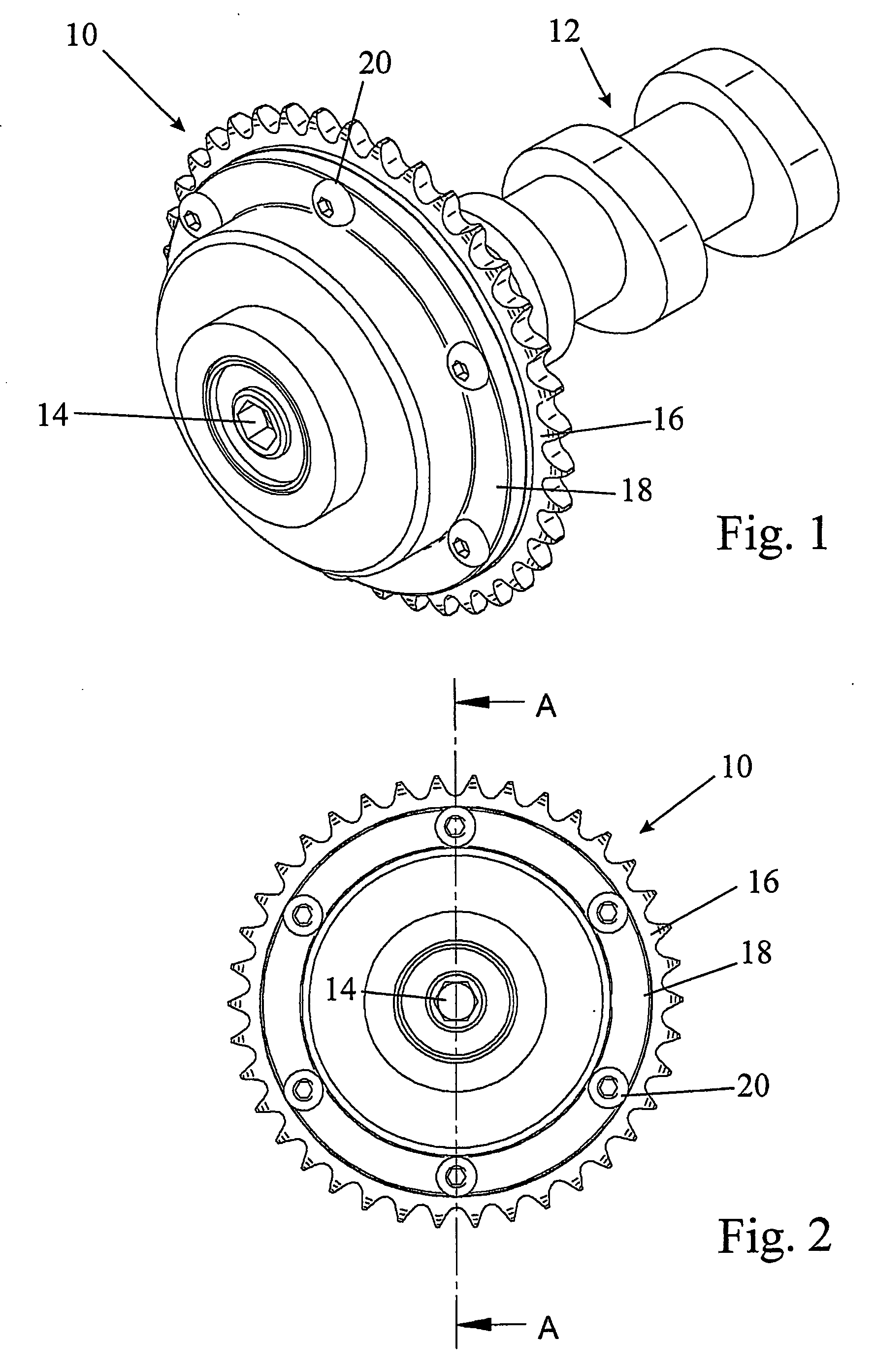
[0021] The phaser 10 comprises a sealed unit filled with a magnetorheological fluid that is fixed by means of a bolt 14 on to the front end of an engine camshaft 12. The casing of the sealed unit is formed of two parts, namely a sprocket 16 that is driven by the engine crankshaft and a dished cover 18 secured to the sprocket 16 by means of bolts 20.

[0022] The flat cylindrical chamber contained between the sprocket 16 and the cover 18 contains a hub 22 which, as shown in FIG. 4, is keyed to the front end of the camshaft 12. Two vanes 24 are located in radial sl...


PUM


Abstract

A hydraulic phase shifting mechanism is described for an engine camshaft subjected to torque fluctuations during operation. The mechanism employs a magnetorheological fluid as a hydraulic pressure medium and is controlled by selective application of a magnetic field to vary the flow properties of the magnetorheological fluid.

Description

FIELD OF THE INVENTION [0001] The present invention relates to a phase shifting mechanism for an engine camshaft. BACKGROUND OF THE INVENTION [0002] Many camshaft phase shifting mechanisms (herein also termed phasers) have been proposed, and are in use, which are actuated hydraulically, often using engine oil. While these phasers have been demonstrated to be effective, they can have a high oil demand, sometimes requiring an auxiliary pump and an associated cost penalty. The presence of large amounts of oil in the engine cylinder head can cause problems with oil drainage and aeration, together with the problems associated with belt contamination in the case of belt driven camshafts. [0003] Furthermore, the use of hydraulic actuation requires a control valve, which can control the oil flow in response to electrical inputs from the engine ECU, and this can have significant cost and packaging implications. [0004] U.S. Pat. No. 5,056,477 discloses a phase shifting mechanism for an engine...

Claims


Application Information

Patent Timeline
Patent Type & Authority Applications(United States)
IPC IPC(8): F01L1/34F01L1/344
CPCF01L1/024F01L1/34F01L1/34409F01L2820/00F01L2001/34483F01L2101/00F01L1/3442F01L2301/00
Inventor LANCEFIELD, TIMOTHY MARK
Owner MECHADYNE INT
Learn More