
Corrodable boring shoes for wellbore casing, and methods of forming and using such corrodable boring shoes

a technology of corrodable boring shoes and wellbore casing, which is applied in the direction of drilling casings, drilling pipes, and wellbore/well accessories, etc., can solve the problems of high cost of operations, time-consuming and laborious, and complex retrieval procedures for recovering drill strings

Active Publication Date: 2012-10-11
BAKER HUGHES INC
View PDF16 Cites 8 Cited by
  • Summary
  • Abstract
  • Description
  • Claims
  • Application Information

AI Technical Summary

Benefits of technology

[0009]Yet further embodiments of the present disclosure include methods of casing a wellbore. In accordance with such methods, a casing shoe having at least one cutting structure is - mounted on an end of a section of casing. The section of casing with the casing shoe thereon into a wellbore. A rate of corrosion of a body of the casing shoe within the wellbore is selectively increased to at least partially corrode the body of the casing shoe. Selectively increasing the rate of corrosion of the body may comprise increase a rate of corrosion of a corrodible matrix phase comprising at least one of a ceramic and an intermetallic compound in which a metallic phase is dispersed. An additional section of casing or drill pipe is advanced through the end of the section of casing and the at least partially corroded body of the casing shoe.

Problems solved by technology

Unfortunately, sequential drilling and casing may be time consuming because, as may be appreciated, at the considerable depths reached during oil and gas production, the time required to implement complex retrieval procedures to recover the drill string may be considerable.
Thus, such operations may be costly as well, since, for example, the beginning of profitable production can be greatly delayed.
Moreover, control of the well may be difficult during the period of time that the drill pipe is being removed and the casing is being disposed into the borehole.

Method used


Image

  • Corrodable boring shoes for wellbore casing, and methods of forming and using such corrodable boring shoes
  • Corrodable boring shoes for wellbore casing, and methods of forming and using such corrodable boring shoes
  • Corrodable boring shoes for wellbore casing, and methods of forming and using such corrodable boring shoes

Examples


Embodiment Construction

[0026]Illustrations presented herein are, in some cases, not meant to be actual views of any particular material, casing shoe, or drilling assembly, but are merely idealized representations which are employed to describe embodiments of the present disclosure. Elements common between figures may retain the same numerical designation.

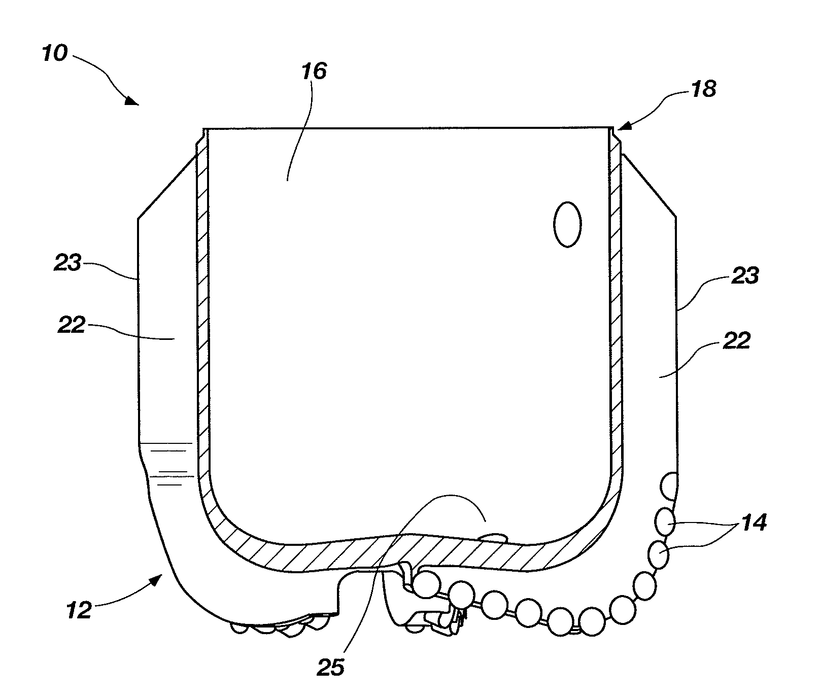
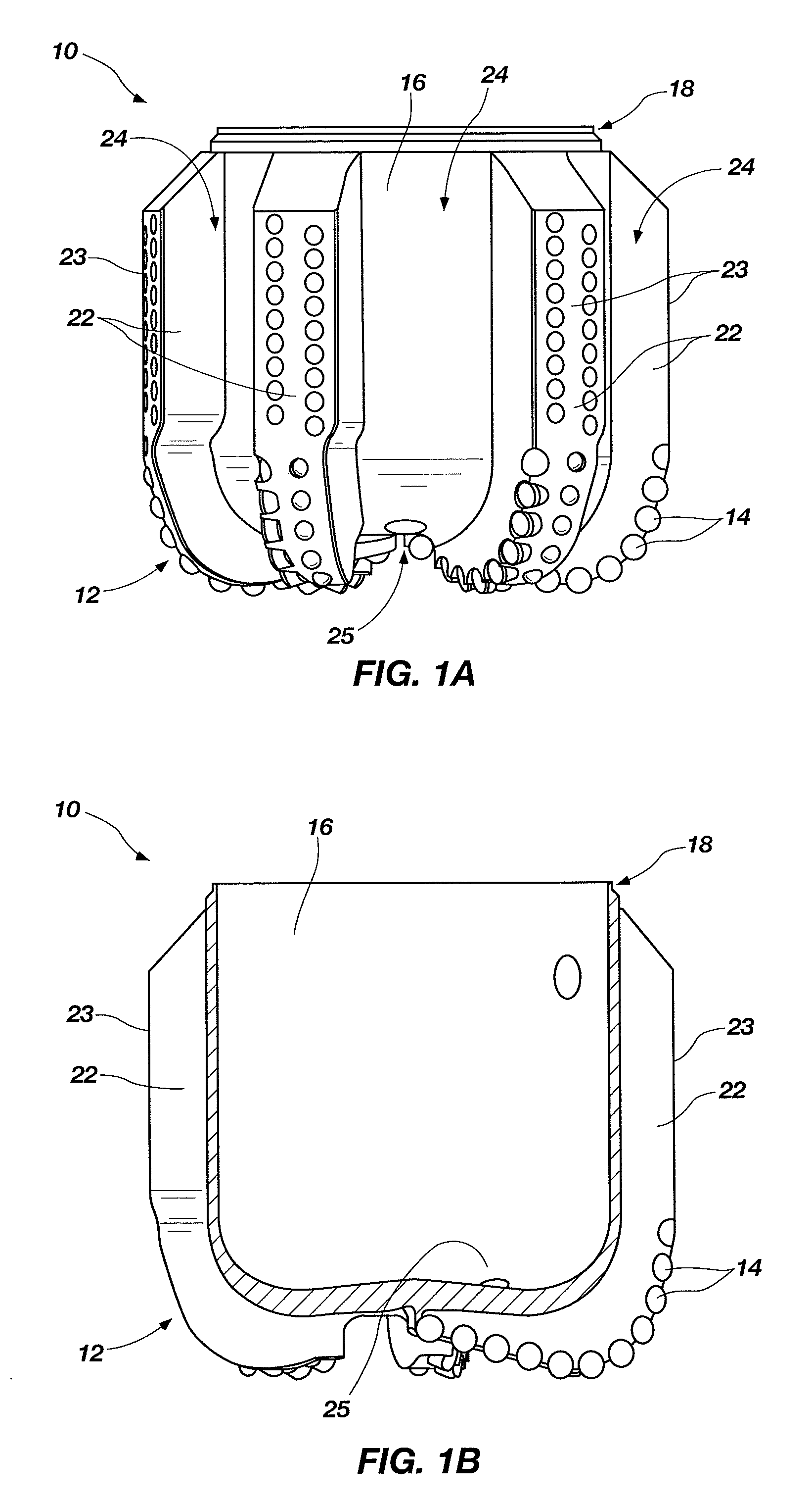
[0027]An embodiment of a casing shoe 10 is shown in FIGS. 1A and 1B. The casing shoe 10 includes a crown 12 configured for drilling a wellbore when the crown 12 is attached to a section of casing and the casing is advanced into a wellbore. Thus, the crown 12 includes at least one cutting structure 14 carried on a body 16 of the crown 12. The crown 12 also includes connection structure 18 configured for attachment to a section of casing. As discussed in further detail below, at least a portion of the body 16 of the crown 12 comprises a composite material that may be selectively corroded after using the casing shoe 10 for a period of service time. Thus, aft...


PUM

PropertyMeasurementUnit
compressive yield strengthaaaaaaaaaa
particle diameteraaaaaaaaaa

Abstract

Earth-boring casing shoes include a crown configured for at least one of drilling and reaming a wellbore when the crown is attached to a section of casing and the casing is advanced into a wellbore. The crown includes a body comprising a corrodible composite material, and at least one cutting structure carried on the body. The casing shoes further include connection structure configured for attachment to a section of casing. Methods are used to form such casing shoes, and such casing shoes are used to install casing within wellbores.

Description

TECHNICAL FIELD[0001]The present invention relates to earth-boring shoes configured for attachment to a section of wellbore casing, to methods of manufacturing such earth-boring shoes, and to methods of adapting such earth-boring shoes for attachment to a section of wellbore casing.BACKGROUND[0002]The drilling of wells for oil and gas production conventionally employs longitudinally extending sections or so-called “strings” of drill pipe to which, at one end, is secured a drill bit of a larger diameter. After a selected portion of the borehole has been drilled, the borehole is usually lined or cased with a string or section of casing. Such a casing or liner usually exhibits a larger diameter than the drill pipe and a smaller diameter than the drill bit. Therefore, drilling and casing according to the conventional process typically requires sequentially drilling the borehole using drill string with a drill bit attached thereto, removing the drill string and drill bit from the borehol...

Claims


Application Information

Patent Timeline
Patent Type & Authority Applications(United States)
IPC IPC(8): E21B19/16B29B15/00B29C71/00E21B17/14B29C67/24B22F1/16
CPCB22F1/02B22F3/04B22F3/10B22F3/14B22F3/24B22F5/00E21B7/20E21B17/14C04B35/62842C22C23/00C22C23/02B22F2005/001B22F1/16
Inventor OXFORD, JAMES ANDY
Owner BAKER HUGHES INC
Learn More