Method for monitoring the operation of a vacuum pump in a brake system
- Summary
- Abstract
- Description
- Claims
- Application Information
AI Technical Summary
Benefits of technology
Problems solved by technology
Method used
Image

Examples
Embodiment Construction
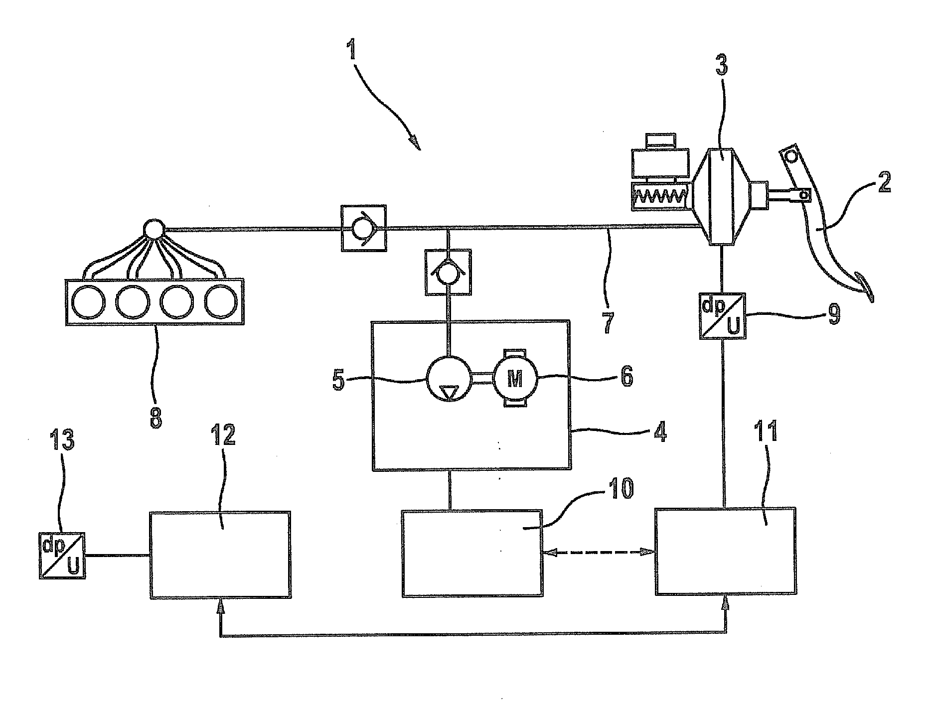
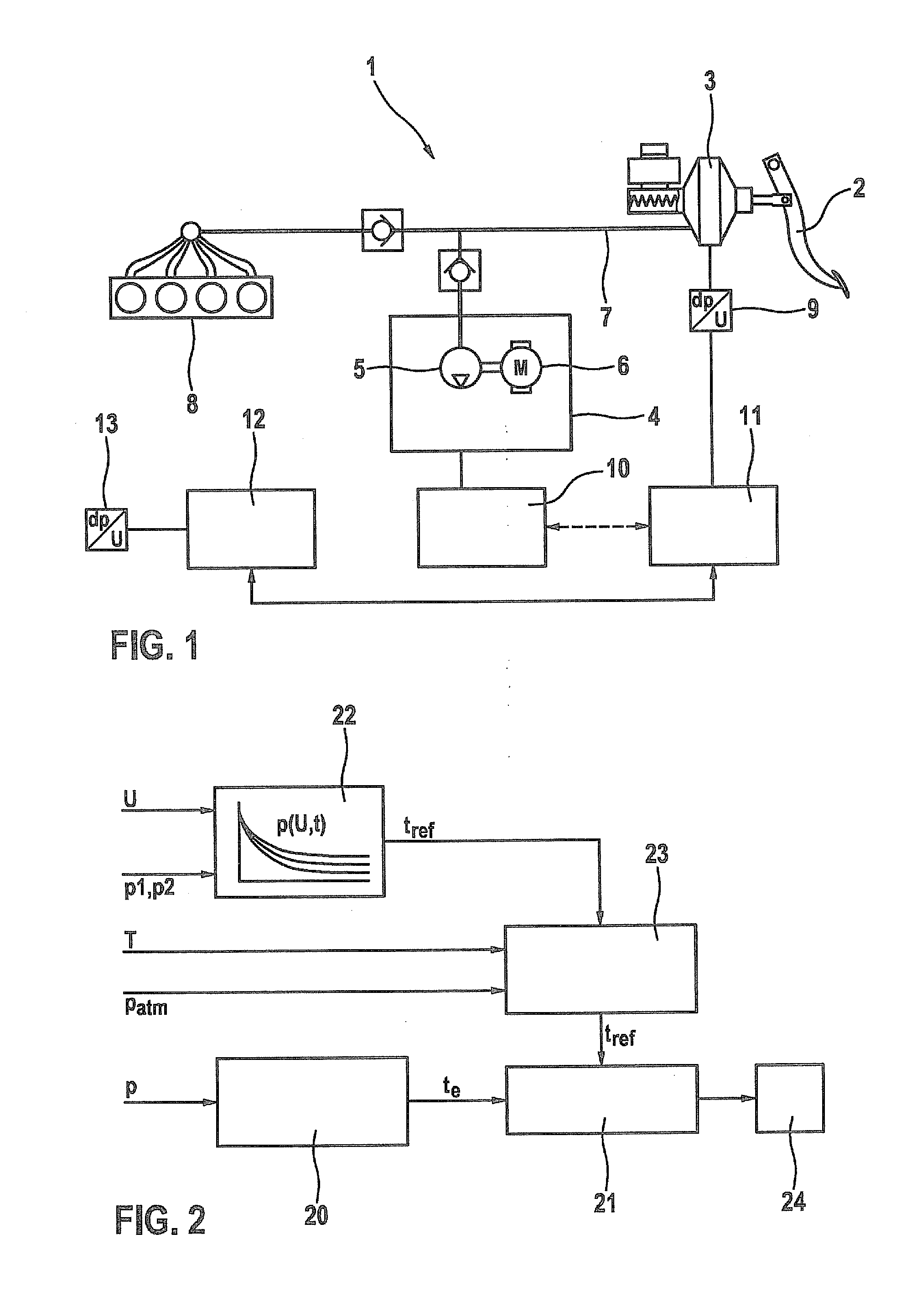
[0026]FIG. 1 shows a brake system 1 which is integrated into a vehicle, brake system 1 being activated via a brake pedal 2 which is coupled with a pneumatic brake booster 3. An electric vacuum pump 4, which has a pump unit 5 and an electric motor 6 for driving pump unit 5, is assigned to pneumatic brake booster 3. Vacuum pump 4 is connected to the vacuum chamber of brake booster 3 via a pressure line 7. The vacuum chamber of brake booster 3 is evacuated during operation of vacuum pump 4, which achieves a brake boosting action to assist the braking process.
[0027]FIG. 1 shows an internal combustion engine 8, which is used as the drive unit of the vehicle and whose intake tract is connected to pressure line 7 via an additional line and thus also to the vacuum chamber of brake booster 3. The pressure reduction in the vacuum chamber of brake booster 3 may be at least partially produced with the aid of internal combustion engine 8 via this connection. A minimum vacuum in brake booster 3 i...
PUM
 Abstract
Description
Claims
Application Information
 - R&D
- Intellectual Property
- Life Sciences
- Materials
- Tech Scout
- Unparalleled Data Quality
- Higher Quality Content
- 60% Fewer Hallucinations
Browse by: Latest US Patents, China's latest patents, Technical Efficacy Thesaurus, Application Domain, Technology Topic, Popular Technical Reports.
© 2025 PatSnap. All rights reserved.Legal|Privacy policy|Modern Slavery Act Transparency Statement|Sitemap|About US| Contact US: help@patsnap.com