Determining cylinder switching of an internal combustion engine
A technology of an internal combustion engine and a cylinder, applied in the field of computer programs
Inactive Publication Date: 2019-04-16
ROBERT BOSCH GMBH
View PDF6 Cites 0 Cited by
- Summary
- Abstract
- Description
- Claims
- Application Information
AI Technical Summary
Problems solved by technology
The cylinder on / off operating state is to be understood as the targeted deactivation and / or activation of at least one cylinder of the internal combustion engine, in particular for a corresponding reduction in fuel consumption (cylinder deactivation), or in the event of an increased torque demand on the internal combustion engine This is achieved by activating or opening the inactive cylinders of the internal combustion engine accordingly
Method used
View moreImage
Smart ImageViewing Examples

Examples
Embodiment Construction
Login to View More PUM
 Abstract
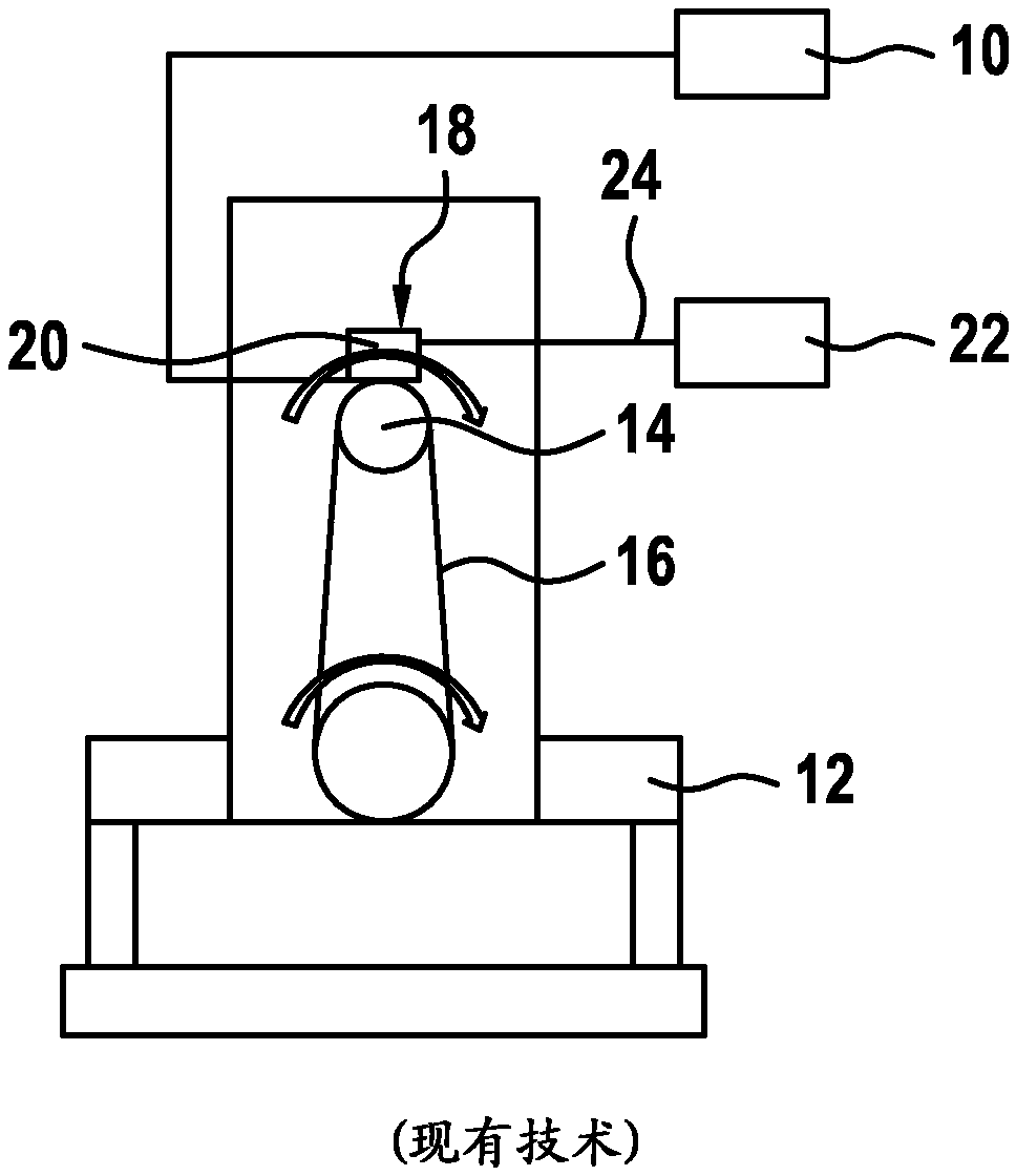
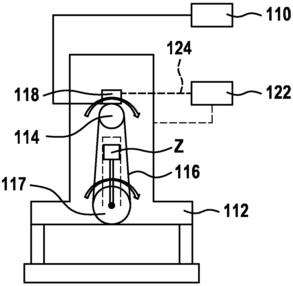
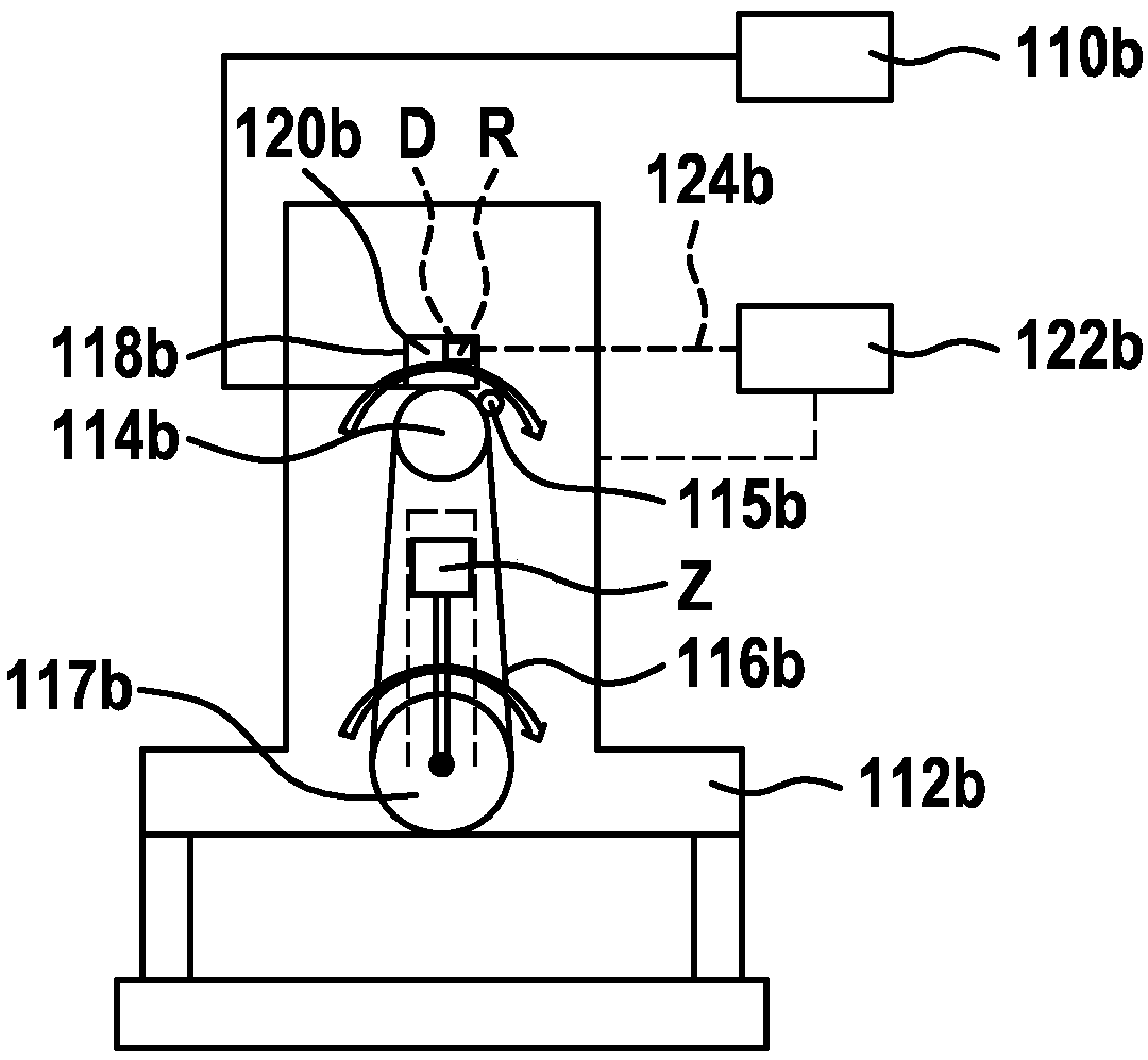
The invention relates to a method for determining cylinder switching (128a) in an internal combustion engine (112), by means of a control unit, preferably a regulator (120) of an electric machine (114) coupled to the internal combustion engine (112). Said method comprises the following steps: determining the temporal course of a rotational speed (122) of an electric machine (114) coupled to the internal combustion engine (112); determining at least one speed pattern (128), produced by the internal combustion engine (112), from the temporal course of the rotational speed (122), the speed pattern (128) having an oscillation (O) superimposed on the temporal course of the mean value (DMD) of the rotational speed (122); then the internal combustion engine (112) is closed to cylinder switching (128a) when a characteristic change in the oscillation (O) is detected for the cylinder switching (128a). Furthermore, the invention relates to a corresponding computing unit (118) which is configuredto carry out the method, to an electric machine (114) comprising the computing unit (118) and to a corresponding computer program for enabling the claimed computing unit (118) to carry out said method.
Description
technical field The invention relates to a method for determining the start and stop of cylinders in an internal combustion engine, as well as to a computing unit, preferably a controller for an electric machine, and to a computer program for carrying out the method. Background technique To regulate the onboard electrical system voltage in a vehicle, electric machines, in particular externally excited electric machines, can be used. The electric machine has a regulator which regulates the field current of the electric machine as a function of the vehicle electrical system voltage. Such an electric machine is known from DE 10 2012 204 751 A1. In addition, so-called intelligent controllers are known which, depending on the operating state of the internal combustion engine detected by the engine controller, correspondingly adjust the field current of the electric machine in order to ensure a correspondingly optimized operation of the internal combustion engine and the electri...
Claims
Login to View More Application Information
Patent Timeline
 IPC IPC(8): F02D41/14F02D41/00F02N11/04G01P3/48G01M15/04H02P9/00H02P29/024F02D41/16F16D48/10
CPCF02D29/06F02D41/0087F02D41/0097F02D41/1497F02D2200/101G01M15/046H02P6/17
Inventor P·梅林格J·马斯U·舒尔茨W·费舍Z·埃塞克
Owner ROBERT BOSCH GMBH
Features
- Generate Ideas
- Intellectual Property
- Life Sciences
- Materials
- Tech Scout
- Unparalleled Data Quality
- Higher Quality Content
- 60% Fewer Hallucinations
Learn More Browse by: Latest US Patents, China's latest patents, Technical Efficacy Thesaurus, Application Domain, Technology Topic, Popular Technical Reports.
© 2025 PatSnap. All rights reserved.Legal|Privacy policy|Modern Slavery Act Transparency Statement|Sitemap|About US| Contact US: help@patsnap.com