
Drive with an energy store device and method for storing kinetic energy

An energy storage and drive technology, applied in the drive field, can solve problems such as the influence of braking performance, and achieve the effect of increasing the throttling effect

Inactive Publication Date: 2009-01-28
HYDROMATIK GMBH
View PDF1 Cites 4 Cited by
  • Summary
  • Abstract
  • Description
  • Claims
  • Application Information

AI Technical Summary

Problems solved by technology

[0003] The described device therefore has the disadvantage of not being able to exert an influence on the braking performance during the recovery of the braking energy

Method used


Image

  • Drive with an energy store device and method for storing kinetic energy

Examples


Embodiment Construction

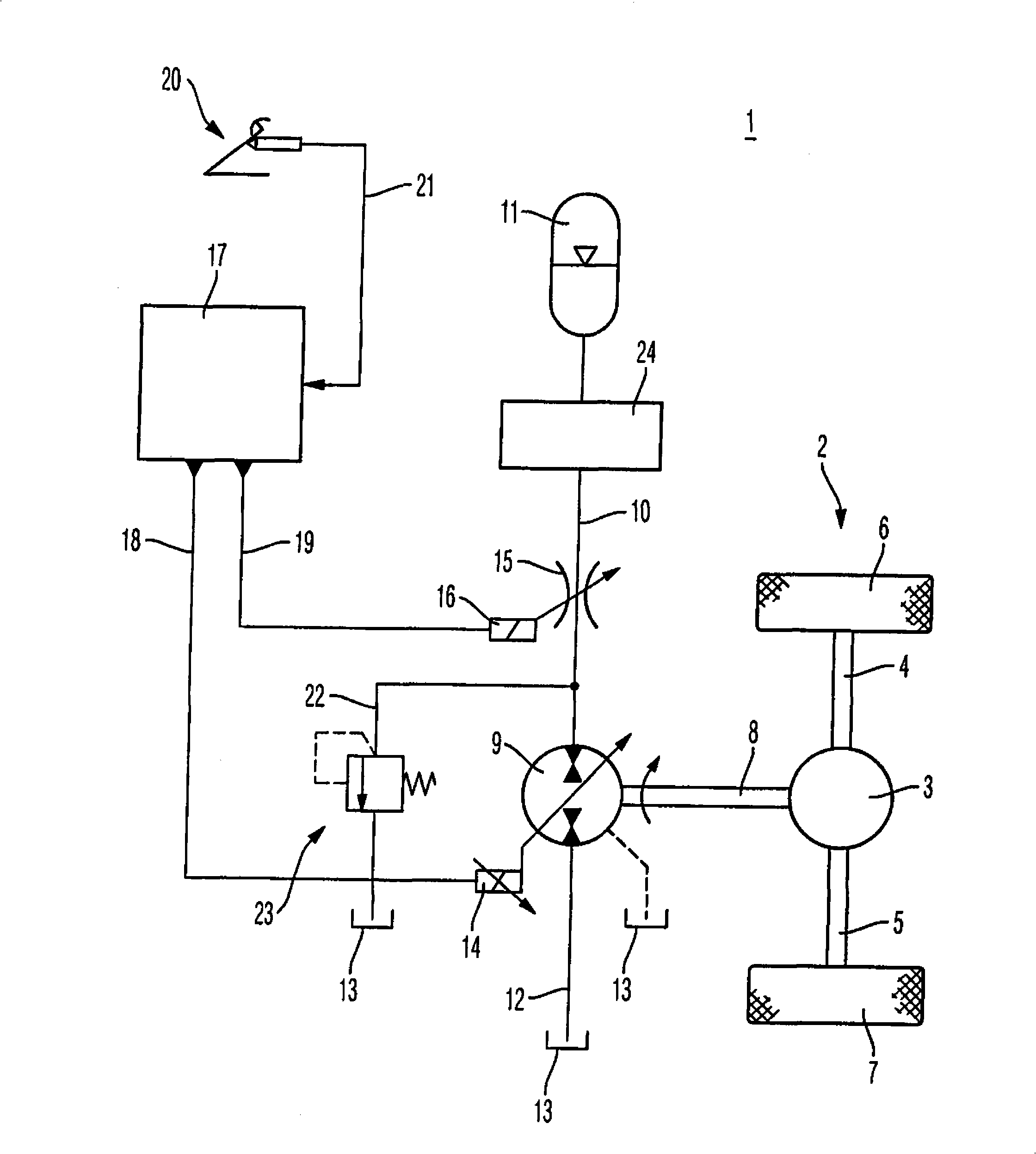
[0013] figure 1 It is a schematic explanatory diagram of the drive 1 according to the present invention. The drive 1 according to the invention is used, for example, to drive a drive shaft 2. The driven drive shaft 2 has a shaft differential 3 which acts on the driven wheels 6, 7 of the vehicle via the first half shaft 4 and the second half shaft 5.

[0014] The drive 1 described is in particular a drive drive of a utility vehicle with a dense drive cycle. For example, in garbage collection vehicles, wheeled excavators, and forklifts, such intensive driving cycles can occur, which involve a large number of braking and then accelerating operations. In order to enable the kinetic energy released during the braking operation to be reused, the drive 1 has an energy storage device. The energy storage device is connected to the drive shaft 2 through a coupling shaft 8. For succinct reasons, the coupling axis 8 is figure 1 Shown in is connected to the rear axle differential 3. However, ...


PUM


Abstract

The invention relates to a drive (1) with an energy store device and to a method for storing braking energy. A drive (1) has an energy store device having a hydrostatic piston machine (9) and a storage element (11) which is connected thereto. Arranged in a high-pressure storage line (10) between the piston machine (9) and the storage element (11) is an adjustable throttle point (15). During braking, the adjustable throttle point (15) is adjusted as a function of a determined demanded braking torque. The pressure medium is fed by the hydrostatic piston machine (9) via the adjustable throttle point (15) into the storage element (11).

Description

Technical field [0001] The invention relates to a drive with an energy storage device and a method for storing kinetic energy. Background technique [0002] In order to store kinetic energy in a vehicle with dense driving cycles (that is, frequent braking and subsequent re-acceleration), it is known, for example, from US 6712166B2 to store kinetic energy in the form of pressure energy. For this purpose, the hydraulic pump is coupled to the travel drive. The hydraulic pump operates as a pump during the braking operation to deliver the pressure medium into the pressure accumulator. Conversely, with a hydraulic pump that can also operate as a hydraulic motor, the pressure accumulator reduced in pressure by the hydraulic pump can restore pressure energy. In the device known from US 6712166B2, a flow control valve is used to maintain the brake pressure at a constant level. [0003] The described device therefore has the disadvantage of not being able to exert an influence on the braki...

Claims


Application Information

Patent Timeline
Patent Type & Authority Applications(China)
IPC IPC(8): B60T1/10
CPCB60T1/10B60K6/12Y02T10/6208Y02T10/62B60K6/08
Inventor 罗尔夫·拉特克克里斯蒂娜·埃雷特马丁·贝姆马蒂亚斯·米勒
Owner HYDROMATIK GMBH
Learn More